


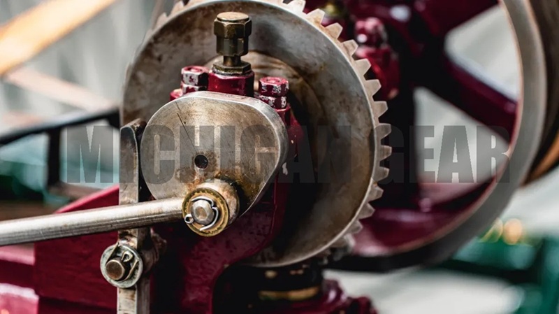
When I look at a bevel gear, I see a cone-shaped tool that helps move power between shafts that meet, often at a 90-degree angle. Its special conical design changes how thick and strong the teeth are, which means it can handle high speeds and last longer while working efficiently.
Key Takeaways
●Bevel gears change the direction of power between shafts, often at a 90-degree angle, making them essential in many mechanical systems.
●Choosing the right type of bevel gear—like straight, spiral, hypoid, or miter—depends on the application, desired efficiency, and noise level.
●Material selection is crucial; steel is best for heavy loads, while plastic or brass works well for lighter, quieter applications.
Types of bevel gear
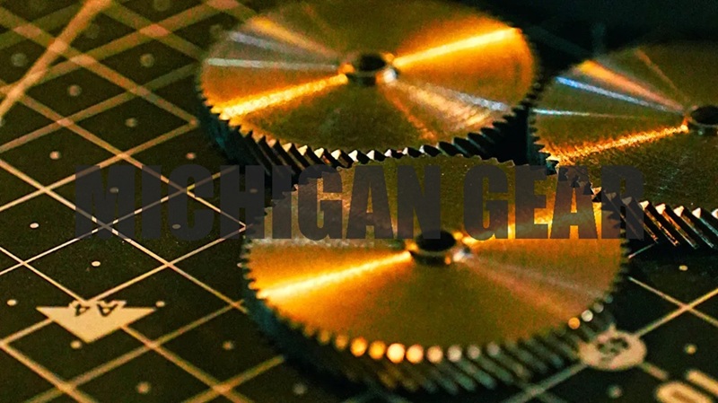
When I study mechanical systems, I notice that bevel gear designs vary based on how they transmit power and fit into different machines. Each type has unique features that affect performance, noise, and efficiency. Let me walk you through the main types.
Straight bevel gear
Straight bevel gears have teeth that run straight and parallel to the cone’s generators. This makes them look like spur gears, but with a conical shape. I find that the tooth trace points directly to the cone apex. When these gears mesh, all the teeth engage and disengage at once along the face width. This causes a sudden impact and creates more noise, especially at higher speeds.
| Feature | Description |
|---|---|
| Tooth Direction | Straight, pointing to cone apex |
| Meshing Characteristic | Simultaneous engagement, high impact and noise |
I often see straight bevel gears used in equipment where simplicity matters more than quiet operation. Some common applications include:
●Food canning equipment
●Food packaging equipment
●Welding positioning equipment
●Lawn and garden equipment
●Machine tools like lathes and mills
●Compression systems for oil and gas
●Fluid control valves
Spiral bevel gear
Spiral bevel gears stand out because their teeth curve along the cone. This curved design allows the teeth to engage gradually, which reduces noise and vibration. I notice that spiral bevel gears operate much more smoothly than straight bevel gears. The larger contact area between teeth also improves efficiency, sometimes reaching up to 98-99%.
●Spiral bevel gears have curved teeth for gradual engagement.
●They run quieter and smoother than straight bevel gears.
●The increased contact area boosts efficiency.
| Industry | Application of Spiral Bevel Gears |
|---|---|
| Locomotives | Used for power transmission |
| Power Plants | Employed in machinery for efficiency |
I often find spiral bevel gears in locomotives and power plants, where smooth and efficient power transmission is essential.
Hypoid bevel gear
Hypoid bevel gears offer a solution for transmitting power between shafts that do not intersect. The axes are offset, which lets me use larger pinions and achieve higher gear ratios. This offset design increases torque transmission and allows for compact installation. I see hypoid bevel gears in automotive rear axles, heavy machinery, and high-performance industrial equipment.
●The offset lets me use larger, stronger pinions for more torque.
●The sliding action and high contact ratio make torque transmission efficient.
●The design reduces vibration and noise.
Hypoid bevel gears are ideal when I need greater strength and a compact setup.
Miter gear
Miter gears are a special type of bevel gear. They have equal tooth counts and usually operate at a 90° shaft angle. When I use a 1:1 gear ratio, the angle splits 45°/45°, which is typical for miter gears. This simple design makes them efficient for changing the direction of power without altering speed or torque.
| Advantages | Limitations |
|---|---|
| Simple Design and Construction | Limited Load-Carrying Capacity |
| Low Cost | Limited Speed Range |
| High Efficiency | Limited Torque Range |
I prefer miter gears when I need a straightforward, efficient solution, but I avoid them in high-load or high-speed situations.
Tip: Choosing the right bevel gear depends on the shaft arrangement, desired efficiency, and noise level. I always match the gear type to the application for the best results.
Bevel gear design & materials
Gear geometry
When I examine a bevel gear, I notice its conical shape. This geometry lets the gear mesh with another at an angle, usually 90 degrees. The tooth shape and pitch angle play a big role in how efficiently the gear transmits power. I pay close attention to the pressure angle and diametral pitch because they affect strength and smoothness. If I optimize the tooth surface, I can improve load distribution and reduce friction. I see that sliding friction losses are higher in spiral and hypoid bevel gears, which lowers efficiency. Under ideal conditions, bevel and hypoid gears reach efficiencies between 93.5% and 98%.
| Factor | Description |
|---|---|
| Tooth Geometry | Determines operational efficiency and ensures accurate meshing with minimal power loss. |
| Pitch Angle | Influences gear design and ensures efficient mesh and operation. |
| Pressure Angle | Affects gear strength and smoothness; consistent angles ensure proper meshing and efficiency. |
| Diametral Pitch | Crucial for determining gear ratios and affects strength, load capacity, and transmission smoothness. |
Common materials
I select materials based on the demands of the application. Steel stands out for its strength and ability to handle high loads. Brass offers durability and resists wear. Plastic works well when weight matters or for quieter operation. Alloy steel gives good impact resistance, while carbon steel provides wear resistance. Hardened steel ensures smooth power transmission and excellent wear resistance.
Tip: I always match the material to the load, speed, environment, and budget. This helps me balance durability and performance.
Manufacturing process
I rely on CNC machining to achieve precise tooth shapes and minimize backlash. Heat treatment boosts hardness and wear resistance, which is vital for gears under heavy loads. Finishing techniques improve tooth contact and reduce noise. I use dimensional inspection tools like CMM and gear analyzers to check accuracy. Hardness testing and metallurgical analysis confirm quality. ISO 9001:2015 certification assures me that the gears are defect-free.
Bevel gear applications
Power transmission
When I work with mechanical systems, I rely on bevel gears to transfer power between shafts that meet at an angle. The conical teeth mesh together, allowing rotational force to move from one shaft to another. This setup works well for non-parallel axes, especially when I need to change the direction of motion. I see that the pinion acts as the driver and rotates, engaging with the bevel gear. This action transmits torque and often results in a speed reduction and torque increase. If I reverse the roles and use the bevel gear as the driver, it rotates and engages with the pinion, leading to a speed increase and torque decrease.
●Bevel gears transmit power between non-parallel axes.
●The pinion drives the bevel gear, increasing torque and reducing speed.
●The bevel gear drives the pinion, increasing speed and reducing torque.
Note: The conical design of bevel gears lets me transfer power efficiently between intersecting shafts, which is essential in many machines.
Speed and torque changes
I notice that bevel gears operate by engaging at the apex of their conical surfaces. This design helps transfer rotational power between shafts at specific angles. The geometry minimizes energy loss and boosts efficiency. I use bevel gears when I need to change speed and torque in mechanical setups. For example, if I want more torque, I select a gear ratio that reduces speed. If I need higher speed, I choose a ratio that decreases torque.
| Property | Bevel gears (miter gears when equal) | Worm drive | Hypoid gear |
|---|---|---|---|
| Max efficient speed | 8,000+ RPM (spiral) | 1,800 RPM | 6,000 RPM |
| Max ratio per stage | 6:1 practical | 100:1 | 10:1 |
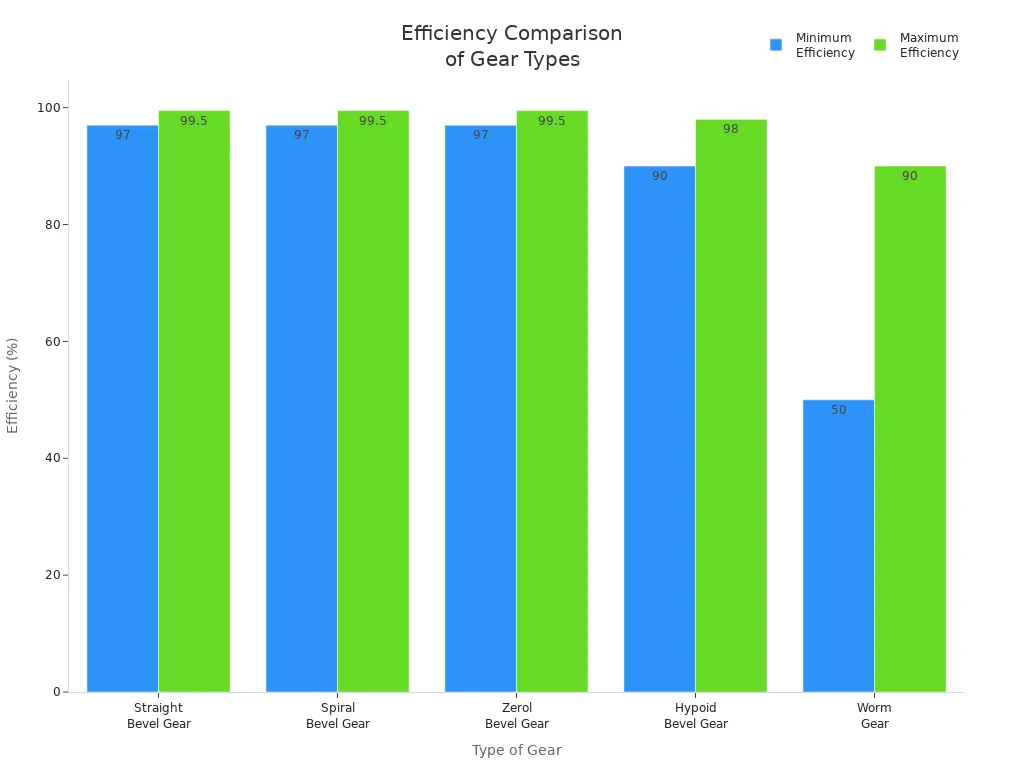
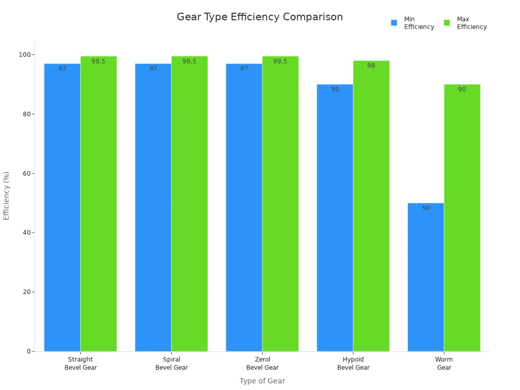
I compare bevel gears to other types and see that they offer high efficiency. The table below shows how different gears perform:
| Type of Gear | Approximate Range of Efficiency |
|---|---|
| Straight Bevel Gear | 97 – 99.5% |
| Spiral Bevel Gear | 97 – 99.5% |
| Zerol Bevel Gear | 97 – 99.5% |
| Hypoid Bevel Gear | 90 – 98% |
| Worm Gear | 50 – 90% |
Tip: I always check the gear ratio and efficiency before choosing a bevel gear for a project. This helps me match the speed and torque to the needs of the machine.
Industry uses
I see bevel gears everywhere in industry. They play a key role in automotive systems, heavy equipment, aviation, marine, and even hand tools. In cars, bevel gears transfer power in differentials, letting wheels rotate at different speeds. This is crucial for smooth turns and safe driving. I use bevel gears in rear axle drives to move power from the engine to the wheels. In all-wheel drive systems, they help distribute power evenly.
●Automotive Industry: Transfers power in differentials and rear axle drives.
●Heavy Equipment: Changes power transmission direction and drives auxiliary units.
●Aviation: Powers helicopter rotors and airplane accessory gear drives.
●Marine Transmission: Moves power in stern drive systems for propulsion.
●Industrial Plant Equipment: Runs cooling tower fans and machinery.
●Hand Tools: Changes rotation direction and controls speed in drills and planers.
●Locomotives: Transmits power for efficient operation.
●Printing Presses: Facilitates power transmission for smooth printing.
Callout: I rely on bevel gears in high-performance systems because they enhance efficiency, durability, and reliability. Their ability to change direction and distribute power makes them essential in many fields.
I find that bevel gears operate on the principle of angular transmission. Their conical teeth engage to transfer rotational power between shafts at specific angles. This design minimizes energy loss and maximizes efficiency, making bevel gears ideal for applications that require directional changes.
I see that choosing the right gear depends on many factors. The table below shows what I consider:
| Factor | Description |
|---|---|
| Tooth Line | The alignment of the teeth affects how well the gears mesh and transmit power. |
| Tooth Depth | Influences the strength and load capacity of the gear. |
| Point of Intersection | The angle at which the shafts intersect can affect the gear’s efficiency and performance. |
I always check efficiency before making a decision.
When I need high efficiency, durability, and smooth power transmission, I choose bevel gears for demanding engineering projects.
FAQ
What is the main advantage of using bevel gears?
I use bevel gears to change the direction of power between shafts. Their design lets me transfer motion smoothly at different angles.
How do I choose the right bevel gear material?
I look at load, speed, and environment. For heavy loads, I pick steel. For quiet or light-duty jobs, I use plastic or brass.
Can bevel gears handle high speeds?
Yes, I use spiral bevel gears for high-speed applications. Their curved teeth reduce noise and vibration, making them ideal for fast-moving machinery.
Post time: Jun-04-2026