


I define a bevel gear as a gear with a conical shape that transmits power between two intersecting shafts. I see its main role in changing the direction of motion and torque, often at a 90° angle. The pitch cone and other geometric features help the gear mesh and operate efficiently. I believe understanding these gears brings practical benefits and helps solve engineering challenges.
Key Takeaways
●Bevel gears change the direction of motion and torque, often at a 90° angle, making them essential in various mechanical systems.
●Choosing the right bevel gear type, such as straight, spiral, or hypoid, depends on specific application needs like load capacity and noise level.
●Regular maintenance of bevel gears, including checking for wear and ensuring proper lubrication, is crucial for long-lasting performance.
Bevel Gear Types
Straight Bevel Gears
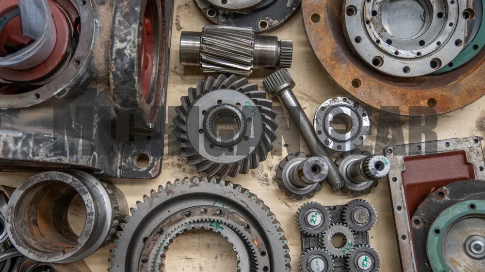
I see straight bevel gears as the most basic form in this category. They feature a conical pitch surface with straight teeth that taper toward the apex. I often use them when I need to transmit power between intersecting shafts, usually at a right angle. Their simple tooth shape makes them easy to manufacture and suitable for many mechanical systems.
●Common applications include:
●Automotive differential drives and transmission systems
●Machinery like lawnmowers and forklifts
●Railroad gearboxes for locomotives
●Driveshafts in construction equipment such as excavators and loaders
●Industrial gearboxes for conveyor systems and elevators
●Special devices like coffee grinders, aircraft engines, and medical equipment
I notice that the tooth shape of straight bevel gears affects their load capacity and efficiency. Here is a table that summarizes these factors:
| Factor | Description |
|---|---|
| Pressure Angle | A larger angle increases tooth strength but raises radial load on bearings. |
| Contact Ratio | A higher ratio reduces stress on individual teeth, enhancing operational life and reliability. |
| Undercutting Risk | Low tooth count and small angles can weaken teeth, affecting load capacity. |
| Force Components | Tangential, radial, and axial forces influence bearing selection and overall gear durability. |
Spiral Bevel Gears
I prefer spiral bevel gears when I need smoother and quieter operation. These gears have curved teeth set at an angle, which allows for gradual and distributed contact between teeth. This design improves meshing and reduces noise.
●Advantages of spiral bevel gears:
●Smoother meshing
●Higher load-bearing capacity
●Lower operating noise
●Higher transmission efficiency
Research shows that spiral bevel gears can reduce noise by up to 16 dB, making them comparable to helical gears. I often use spiral bevel gears in industries where performance and reliability matter most. Here is a table showing typical applications:
| Industry/Application | Description |
|---|---|
| Automobile Differential | Efficiently transfer power, allow different wheel speeds during turns, enhance comfort and service life. |
| Helicopter Rotor Drive System | Enable 90-degree power transmission, handle large torque, maintain flight stability. |
| Crusher | Handle heavy loads and harsh conditions in mining machinery, ensure stable operation. |
| Robot Joint | Provide precise control and flexible movement, ideal for compact designs. |
| Wind Turbine Gearbox | Facilitate direction conversion, ensure stable operation under low-speed, high-torque conditions. |
Zerol Bevel Gears
I find Zerol bevel gears interesting because they combine features of straight and spiral bevel gears. Their teeth have a zero spiral angle, which aligns the ends of the teeth with the axis. This geometry provides more stable meshing and a smaller impact during operation. I can select smaller modules for these gears, which helps in compact designs.
●Typical application scenarios:
●Automotive differential and axle projects, where stable meshing and repeatable contact pattern control are needed
●Robotic systems and joint stages, offering smooth motion and compact layouts
●Industrial equipment such as machine tools, printing and packaging machines, and test benches, where quieter operation and consistent gear mesh are important
Hypoid Bevel Gears
Hypoid bevel gears share similarities with spiral bevel gears, but their pitch surfaces are not conical. I use hypoid gears when I need to transmit power between offset, non-intersecting shafts. This arrangement increases load capacity and allows for a larger pinion diameter, which results in smoother mesh.
●Key differences between spiral and hypoid bevel gears:
| Gear-set type | Shaft relationship | Main strength | Main limitation |
|---|---|---|---|
| Spiral bevel gear | Intersecting shafts | Smoother meshing, higher load capacity | Axial force, matched-pair sensitivity, complex processing |
| Hypoid gear | Offset, non-intersecting | Stronger load capacity, compact design | Higher sliding, lubrication sensitivity |
●Common uses in automotive engineering:
●Differential systems, allowing wheels to rotate at different speeds for better handling
●Vehicle design improvements, such as lower truck frames for enhanced space, stability, safety, aerodynamics, and fuel efficiency
Miter Bevel Gears
Miter bevel gears stand out because they have a 1:1 gear ratio and typically operate at a 90-degree shaft angle. I use them when I need to change the direction of rotation without altering speed or torque. Their stability under load and noise control are crucial in many applications.
| Characteristic | Description |
|---|---|
| Shaft Angle | Typically 90 degrees |
| Ratio | 1:1 (same tooth count) |
| Functionality | Changes direction without changing speed |
| Application Importance | Stability under load and noise control are crucial |
●Typical machinery where I implement miter bevel gears:
●Bevel gear generators
●Planers
Tip: I always choose the bevel gear type based on the specific requirements of my application, such as shaft arrangement, load capacity, and noise level. Each type offers unique advantages that help me solve different engineering challenges.
Bevel Gear Manufacturing Processes
Cutting and Machining Methods
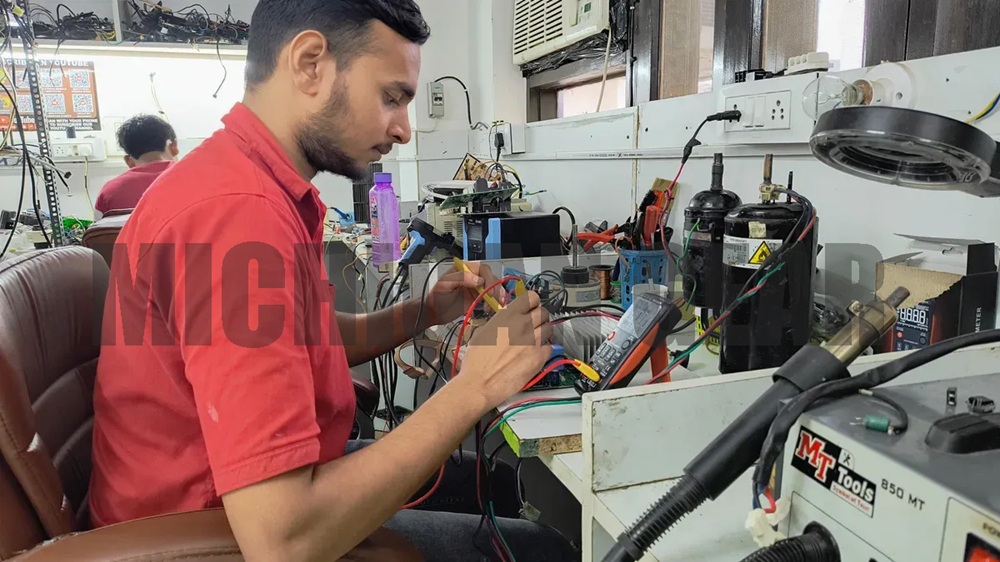
I start the bevel gear manufacturing process with cutting and machining. This step sets the foundation for all later work. If I use poor blanks, I cannot fix them with good cutting, and grinding only corrects small errors. The main steps include:
●Cutting, which shapes the gear teeth and defines their accuracy.
●Grinding and finishing, which improve the tooth profile, surface roughness, and micro-geometry.
●Lapping and contact tuning, which refine the tooth contact pattern and smooth out surface irregularities.
These steps help me achieve high precision and quiet operation, especially in high-speed applications.
Gleason and Klingelnberg Methods
I often choose between the Gleason and Klingelnberg methods for bevel gear production. Each method has unique features and applications.
| Feature | Gleason Bevel Gears | Klingenberg Bevel Gears |
|---|---|---|
| Tooth Design | Spiral & Hypoid | Cyclo-Palloid Spiral |
| Key Technology | Coniflex® | Cyclo-Palloid System |
| Machines | Phoenix, Genesis | Oerlikon C-Series |
| Main Applications | Automotive, Aerospace | Wind Energy, Marine |
I select the method based on the gear design and the industry requirements.
Heat Treatment and Finishing
Heat treatment plays a key role in making gears strong and durable. I use methods like carburizing, quenching, and nitriding to increase hardness and wear resistance. Heat treatment also improves strength, fatigue resistance, and relieves stress from earlier steps. After heat treatment, I use finishing techniques such as CNC machining and surface treatments. These steps:
●Enhance the mechanical properties of the tooth surface.
●Improve durability under high-load conditions.
●Reduce friction and noise.
This process helps prevent premature failure and ensures the gear performs well in demanding environments.
Quality Control
I always check the quality of each bevel gear before it leaves the factory. I measure important parameters to ensure precision and reliability.
| Parameter | Description | Impact on Performance |
|---|---|---|
| Tooth Geometry | Shape and alignment of gear teeth | Affects noise and vibration |
| Runout | Deviation of the gear’s rotational axis | Influences load capacity and lifespan |
| Spacing | Distance between gear teeth | Reduces wear and enhances efficiency |
| Total Composite Error | Combined variations from the ideal gear profile | Ensures precision in gear manufacturing |
By following these steps, I make sure each gear meets high standards for performance and durability.
Bevel Gear Applications
Automotive Differentials
I often rely on bevel gears in automotive differentials to improve vehicle performance. These gears adjust the speed difference between the left and right axles. This adjustment is essential when a car turns, allowing each wheel to rotate at the correct speed. I see bevel gears as the main component that transfers engine power to the wheels. This system helps maintain handling and stability, especially during sharp turns.
●Bevel gears enable the left and right wheels to rotate at different speeds.
●They facilitate efficient power transfer from the engine to the wheels.
●This mechanism enhances overall vehicle performance and safety.
Industrial Machinery
I use bevel gears in industrial machinery to transmit motion between shafts at right angles. Their conical design allows for efficient power transmission with minimal energy loss. Conveyor systems often depend on bevel gears to change the direction of drive motion. I appreciate their ability to handle heavy loads and maintain stability.
| Advantage | Engineering Meaning | Practical Impact |
|---|---|---|
| Direction change capability | Transfers torque between intersecting shafts | Enables compact 90° transmission |
| High transmission efficiency | Single-stage efficiency up to 98% | Reduces energy loss |
| Compact structural form | Suitable for space-constrained housings | Improves packaging flexibility |
Aerospace Systems
I see bevel gears as critical in aerospace systems. They transmit power from engines to propellers or rotors, which improves efficiency and reduces weight. Actuation systems use bevel gears to control flight surfaces, ensuring precise movement. Landing gear mechanisms depend on these gears to handle substantial loads during takeoff and landing. Spiral bevel gears often exceed 95% efficiency, minimizing power loss and enhancing reliability.
| Parameter | Specification | Rationale |
|---|---|---|
| Reliability | >99.999% | Flight safety critical |
| Weight | Minimize | Fuel efficiency, payload |
| Temperature | -55°C to +150°C | Operating envelope |
| Tolerance | AGMA Class 12+ | Zero-failure tolerance |
Power Tools and Equipment
I choose bevel gears for power tools and equipment because they transmit rotation and torque at a 90-degree angle. This feature is essential for compact designs. Bevel gears handle various load types, making them versatile for different tools. Their conical shape allows for space-saving layouts and efficient torque transfer.
1.Bevel gears transmit power at right angles, ideal for compact equipment.
2.They manage high torque, suitable for heavy-duty applications.
3.Their design supports efficient load handling and durability.
Note: I always check for signs of gear wear, misalignment, or overheating in power tools. Regular maintenance prevents unexpected downtime and ensures reliable performance.
I see that each bevel gear type and process offers unique strengths. Knowing where and how to use them helps me make better choices. When I select and maintain bevel gears, I always:
●Check the gear ratio for efficient power transfer.
●Review gear dimensions and tolerances.
●Examine the manufacturing process for quality.
●Assess supplier reputation.
FAQ
What is the main advantage of using spiral bevel gears?
I choose spiral bevel gears for smooth, quiet operation. Their curved teeth reduce noise and vibration. I often use them in automotive and aerospace systems.
How do I maintain bevel gears for long life?
●I check for wear and misalignment.
●I keep gears clean and well-lubricated.
●I replace damaged gears quickly.
Can I use bevel gears for high-speed applications?
| Gear Type | High-Speed Suitability |
|---|---|
| Spiral Bevel | Yes |
| Straight Bevel | Limited |
| Hypoid | Yes |
I select spiral or hypoid bevel gears for high-speed needs.
Post time: Jul-06-2026