


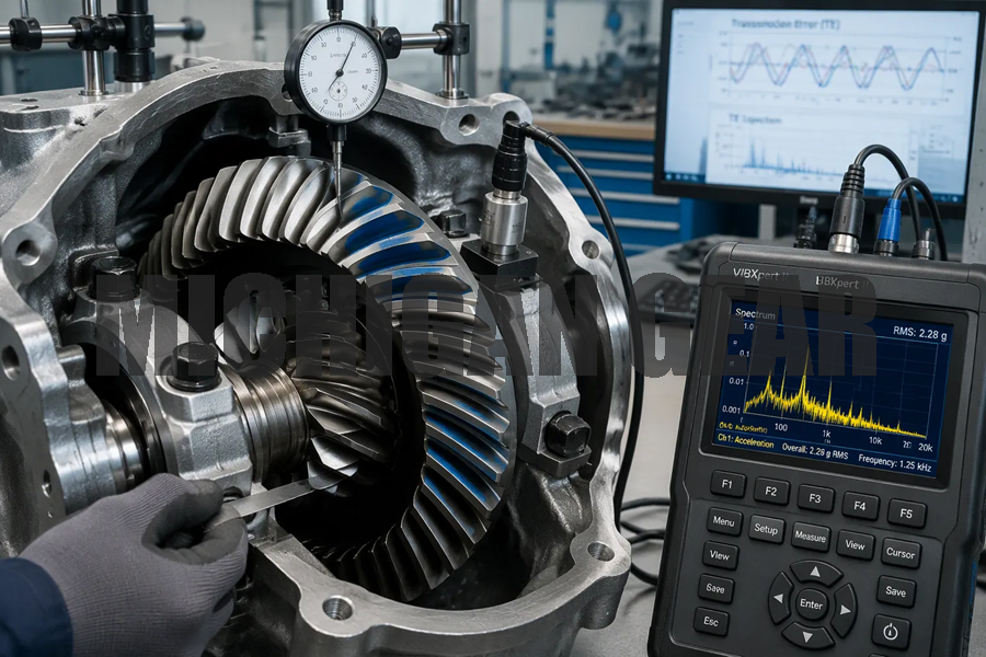
You can cut noise, vibration, and wear in three ways: optimize tooth geometry and design, control manufacturing and assembly precision (backlash and contact pattern above all), and follow disciplined lubrication and maintenance. Spiral bevel gear sets already run smoother and quieter than straight bevel gears, because their curved teeth engage gradually. Any remaining problem is usually specific and correctable.
Four terms help you follow the fixes. Backlash is the small clearance between meshing teeth. Axial overlap is how far the curved teeth overlap along the axis. Transmission error is the tiny mismatch between where a driven gear should be and where it actually sits. Contact pattern is the footprint where teeth touch under load.
Treat noise, vibration, and wear as signals, not as fixed traits.
Key Takeaways
●Optimize tooth geometry and design to reduce noise and vibration.
●Control manufacturing and assembly precision, especially backlash and contact pattern.
●Follow disciplined lubrication and maintenance practices to minimize wear.
●Treat noise, vibration, and wear as signals for targeted fixes.
●Apply fixes in order: design first, then assembly, then maintenance.
Reducing Noise in Spiral Bevel Gear Applications
Causes of Gear Noise
Transmission error is the quiet culprit behind most gear whine. This metric measures the gap between the ideal and actual position of the driven gear as teeth roll through mesh. Gear Technology notes that transmission error stands as a crucial metric for quantifying gear noise levels. The same source traces gear noise to two origins: impact noise from teeth entering mesh, and resonance from eccentricities and other long-term errors. A transmission error curve can predict resonance noise, yet impact noise stays unpredictable.
Spiral bevel gears remain a main source of vibration and noise in gearboxes, according to Gear Technology. Three mechanisms drive that reputation:
●Discontinuities in transmission error generate vibration and noise, and removing them lowers the vibration and noise caused by the mesh.
●Sound power at the meshing frequency dominates the noise signature.
●Assembly errors turn the transmission function piecewise linear, which raises the amplitude of geometric transmission error at the tooth pair transition point.
That last effect deserves attention. Gear Technology explains that this larger amplitude harms dynamic performance and can even cause the teeth to mesh apart in severe cases. You often hear the result as a once-per-revolution tone that climbs with speed.
Design Fixes for Quiet Operation
Overlap ratio offers the first and cheapest lever. Contact ratio is the average number of teeth in contact at any moment. Chamolgear reports that spiral bevel gear designs typically reach 1.8 to 2.5, with most at or above 2. PTSMake notes that a high ratio above 1.2 delivers smooth, quiet running, while a low ratio below 1.2 runs rough and noisy. Curved teeth engage gradually, so they raise the contact ratio and spread load across more teeth. A design that keeps more teeth sharing the load also lowers stress on each tooth and extends durability, PTSMake adds.
| Contact Ratio | Operational Effect |
|---|---|
| Low (below 1.2) | Rough, noisy |
| High (above 1.2) | Smooth, quiet |
Tooth geometry modification attacks transmission error directly. Aerospace research on the OH-58D helicopter main-rotor drive, reported by cmgear.us, showed that optimized spiral bevel gear designs cut noise by 16 dB at 100 percent torque against baseline designs, while also lowering pinion tooth stresses. Modified tooth geometry that minimized transmission error produced that gain. The lesson transfers to industrial drives: geometry work pays off before you touch hardware.
Cutter blade profile correction handles edge contact. You reshape the tooth surface at specific zones so contact stays inside the flank instead of running to the toe or heel. Common corrections include crowning, tip relief, and lead crowning, as zhygear.com lists. Edge contact concentrates stress on a narrow strip and shortens life. These modifications keep the contact pattern centered and stop the sharp load spikes that radiate as noise.
Helix angle optimization works alongside these steps. Increasing the helix angle, often called high helix, produces smoother tooth engagement and less noise, per zhygear.com. Surface finishing matters too. Grinding or honing the flanks improves surface quality and reduces friction-driven noise.
Controlling Vibration in Spiral Bevel Gear Systems
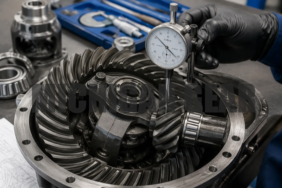
Sources of Spiral Bevel Gear Vibration
Vibration in a spiral bevel gear drive rarely comes from one place. It builds from the mesh itself and from the hardware around it. Transmission error excites the system at the meshing frequency, and any error in the housing or bearings adds its own contribution.
Installation errors deserve close attention. According to zhygear.com, these errors arise from tolerances in housing bores, bearing fits, thermal expansion, and assembly practice. Each one introduces a small misalignment between the gear and pinion axes. That misalignment disrupts the ideal meshing geometry and alters the transmission error spectrum, which zhygear.com calls a key excitation source for noise and vibration. Shaft angle error matters most here. It changes the shape of the transmission error curve and sharpens the force transition, which can lower the contact ratio and feed vibration. Shaft offset and small intersection-angle errors mainly shift the contact path a little. The shaft angle error is the one to watch in noise-critical and vibration-critical drives.
Resonance is the second source. Every gearbox has natural frequencies, and a mesh frequency that lands near one amplifies the response. You see this as a narrow speed band where noise and vibration spike, then fall away again.
Assembly and Damping Techniques
Assembly control removes the excitation you cannot design out. Set backlash to the drawing value, check the contact pattern under light load, and verify shaft alignment with the housing in its working thermal state. A gearbox that runs loose develops mechanical problems fast, and correct assembly keeps backlash tight enough for smooth operation.
Damping adds a second line of defense. A passive ring damper dissipates frictional energy between the damper and a groove machined into the gear web. Research reported by ieee-sensorsalert.org modeled this arrangement and measured its effect:
| Aspect | Detail |
|---|---|
| Damping method | Passive ring damper using friction between damper and a groove in the gear web |
| Most influential parameter | Axial width of the damper, with a significant and linear effect |
| Width increased from 1.5 mm to 2 mm | 5-ND resonance amplitude fell from 15.5 µm to 4.2 µm; dynamic stress dropped from 123.5 MPa to 43 MPa; up to 65% vibration reduction |
| Strain without damper | Maximum 643.7 µε at the 5-ND mode |
| Strain with 2 mm damper | 225 µε, close to model predictions |
| Durability | Archard’s theory showed stable performance over 10⁸ vibration cycles |
The same source offers practical design guidance. Place the damper groove near the gear root, maximize axial width within the available space, and keep radial thickness low enough that damper mass stays below 5% of the gear mass. That last limit protects the balance and inertia you worked to achieve in the original design.
Minimizing Wear in Spiral Bevel Gears
Root Causes of Accelerated Wear
Curved teeth engage gradually, so load spreads across several teeth at once. That gradual contact lowers the sliding speed at each tooth pair and cuts wear compared with straight bevel gears. When wear still runs ahead of schedule, the cause usually traces to lubrication or load.
Chamolgear lists four drivers of accelerated wear: insufficient lubrication that leaves no effective oil film, contaminated lubricant carrying metal fragments or dust, tooth surfaces with insufficient hardness, and misalignment or prolonged heavy-load operation that raises localized contact pressure. Pitting and spalling follow the same pattern, starting as contact fatigue and growing into surface damage.
Poor operating habits add shock loads. Zhygear notes that dropping the clutch or braking suddenly pushes transient torque far above the rated continuous torque, which plastically deforms contact points and starts micro-cracks. A biased implement load or frequent high-speed turns does similar damage over time.
Lubrication and Maintenance Practices
Lubricant choice sets the wear rate. Spiral bevel gears carry higher lubrication demands than straight or zerol types and need circulating oil or oil immersion, per Chamolgear. Viscosity matters in both directions: too thick adds drag, too thin lets the film break, and Wenlio notes the oil film decides friction mode and wear rate. Match the oil grade to the application, since Zhygear shows that using GL-3 where GL-5 is specified raises operating temperature and accelerates pitting.
Set a schedule you actually follow. Welleshaft recommends heavy-duty machinery every 250 operating hours and manufacturing lines every 500 operating hours or per OEM guidelines. Avoid mixing brands and over-lubricating, and filter contaminants from the oil.
Loose hardware destroys adjustment. Zhygear warns that loose mounting bolts let housing halves shift under load, changing backlash and contact pattern during operation. Replacing a pinion front bearing alters axial position, and a 0.1 mm axial shift changes backlash by about 0.07 mm at a 35-degree spiral angle. Recheck backlash and contact pattern after any such change.
Precision Manufacturing and Quality Control
Gear Grinding and Inspection
Grinding is the step that turns a heat-treated gear into a finished one. Heat treatment distorts teeth, and grinding removes that distortion while connecting the earlier manufacturing steps to the final tooth surface, as Chamolgear explains. The payoff shows up across the whole drive:
●Improved gear accuracy
●Reduced noise and vibration
●Controlled tooth surface roughness
●Better contact and meshing performance
●Stable long-term operation
Inspection goes beyond dimensions. Chamolgear notes that ground spiral bevel gears also get a meshing check before delivery, covering contact pattern position, shape, and area, plus backlash, noise, vibration, transmission smoothness, shaft angle, mounting distance, concentricity, and perpendicularity. Magnetic particle testing follows grinding on every gear to catch grinding burn cracks, heat treatment defects, and material or forging flaws.
Dimensional work relies on gear measuring machines and coordinate measuring machines, per xrf-gear.com. Welleshaft cites typical tolerances of plus or minus 0.01 mm for tooth profile accuracy and 0.01 to 0.05 mm for backlash. Non-destructive methods such as dye penetrant and ultrasonic testing reveal internal cracks and inclusions that a visual check would miss.
Contact Pattern Verification
The contact pattern tells you whether the assembly is right. You apply marking compound to a few teeth, rotate the pair under a light braking load, and read the footprint. Gear Technology defines a correct light-load pattern as central toe contact, with load carried toward the toe end and kept inside the tooth boundaries, away from any edge.
Diagnosis follows a simple logic. A pattern near the toe points to pinion position or backlash; one near the heel points to gear mounting or bearing support, per Pairgears. Adjust the pinion axially with shims first, then shift the large gear with its side adjusters while holding bearing clearance constant. ZHY Gear advises two or three iterations, prioritizing the forward drive pattern and tooth height over perfect width centering. A full, elliptical, centered dynamic pattern confirms the adjustment is correct.
You now have three levers for quieter, smoother running: smart design (tooth profile, overlap ratio, transmission error control), precision manufacturing and assembly (backlash, contact pattern), and proactive lubrication and maintenance. Together they deliver quieter operation, lower vibration, longer gear life, and less downtime and cost.
Treat noise, vibration, and wear as diagnostic signals. Apply fixes in order: design first, then assembly, then maintenance. This sequence saves time and money.
Looking ahead, monitoring and preventive practices will keep your spiral bevel gear drives healthy. Track vibration trends, check contact patterns at service intervals, and refresh lubricant on schedule. Small habits prevent large failures.
FAQ
What causes gear whine in a spiral bevel gear drive?
Transmission error drives most whine. The driven gear lags or leads its ideal position as teeth roll through mesh. That mismatch excites the housing at the meshing frequency. Assembly errors make it worse by turning the transmission function piecewise linear. You often hear the result as a once-per-revolution tone that climbs with speed.
How often should you change the lubricant?
Follow the OEM schedule first. For heavy-duty machinery, change oil every 250 operating hours. For manufacturing lines, use 500 operating hours or the OEM guideline. Avoid mixing brands, and filter contaminants from the oil. A clean, correctly graded lubricant keeps the film intact and slows wear.
Why does backlash change after you replace a bearing?
A pinion front bearing sets the axial position of the pinion. A 0.1 mm axial shift changes backlash by about 0.07 mm at a 35-degree spiral angle. Recheck backlash and contact pattern after any bearing change. Loose mounting bolts cause the same drift under load.
Where should the contact pattern sit?
A correct light-load pattern sits at the central toe, with load carried toward the toe end and kept inside the tooth boundaries. A pattern near the toe points to pinion position or backlash. One near the heel points to gear mounting or bearing support. Adjust the pinion with shims first.
Can you cut noise without redesigning the gear set?
Yes, up to a point. Set backlash to the drawing value, verify shaft alignment in the working thermal state, and confirm the contact pattern under light load. A passive ring damper can cut vibration substantially. Design changes deliver the largest gains, though. Optimized geometry has produced noise reductions up to 16 dB.
Post time: Nov-04-2026