


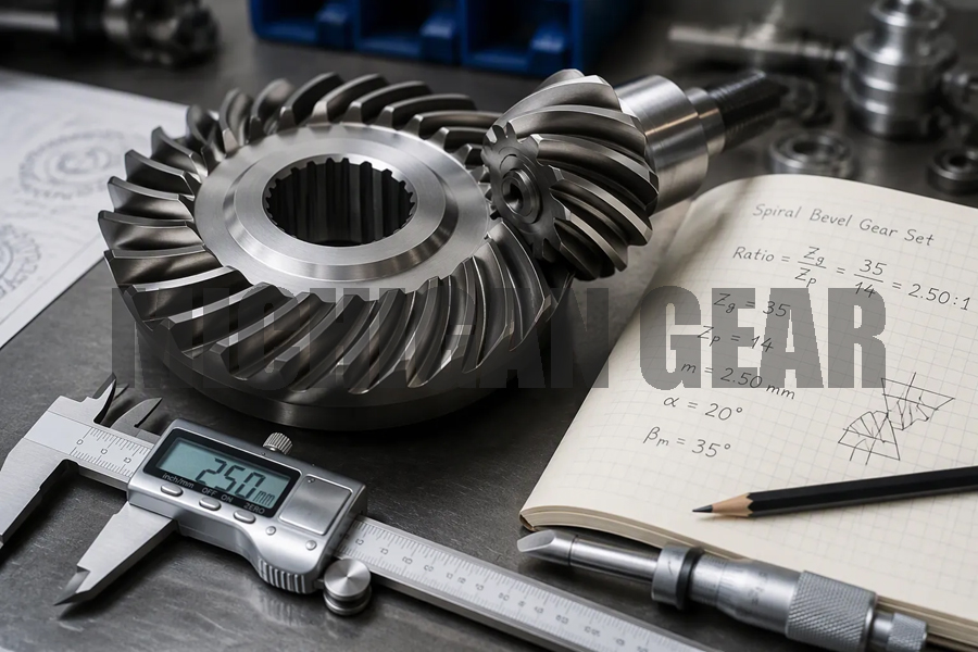
Module governs the size of a spiral bevel gear. You convert torque and rotational speed through the gear ratio, select allowable stress from material and safety factor, then solve standard formulas for module and pitch diameter. Four stages follow: design load and power, ratio conversion to the pinion, material and allowable stress, module and pitch diameter.
Start with the required gear ratio. A 90° shaft angle, 20° pressure angle and 35° spiral angle is a common starting point for bevel gear design. This bevel gears design guide handles units, gives each formula, and works one example. Bevel gears design rewards care with load and power, and spiral bevel gears repay it at every rpm.
Key Takeaways
- Start with torque and speed at the driven gear. Apply a service factor to get design torque.
- Use the gear ratio to find pinion torque and speed. Include efficiency losses for accurate sizing.
- Choose a material and safety factor to set allowable stress. This limits the gear size.
- Calculate the module from bending stress. Round up to the next standard size for strength.
- Convert module to pitch diameter using the spiral angle. Check thrust and mounting before finalizing.
Determine Spiral Bevel Gear Inputs
You begin every bevel gear design with two numbers at the driven gear: input torque (T) and rotational speed (n). Record torque in N·m or lb·in and speed in rpm. These two values anchor the whole calculation, so confirm them against the motor nameplate or the driven machine’s duty cycle before you proceed.
Real machinery rarely delivers smooth torque. A service factor (Kₛ) scales the nominal torque up to a design torque: T_design = T × Kₛ. Pick Kₛ from the load class and daily operating hours.
| Operating Hours/Day | Uniform Load | Moderate Shock | Heavy Shock |
|---|---|---|---|
| Up to 2 | 1.00 | 1.25 | 1.75 |
| 3–10 | 1.25 | 1.50 | 2.00 |
| Over 10 | 1.50 | 1.75 | 2.25 |
Add 0.25 for continuous 24-hour duty, 0.25–0.5 for frequent starts, and 0.5 for reversing operation. A reversing drive may call for a reversing-duty unit instead.
Power follows from torque and speed. In SI units, power in watts = (2π × n × T) / 60, with n in rpm and T in N·m. In imperial units, power in horsepower = (n × T) / 63,025, with T in lb·in. Tangential force at the pitch circle then comes from F_t = 2T / d, where d is the pitch diameter. This force drives the stress-based sizing later. Picture bevel gears as spinning cones with meshed teeth; torque transmission passes across that cone contact.
Define the Gear Ratio of Bevel Gear
The gear ratio of bevel gears equals the number of teeth of the driven gear divided by the number of teeth of the driving gear. You can also derive it from speeds: ratio = input speed / output speed. This speed ratio sets the pinion’s required gear ratio before any sizing begins.
Confirm Spiral Bevel Gear Thrust
Spiral bevel gears generate axial thrust from the spiral angle. Confirm the thrust direction and magnitude early, because bearings and housing stiffness constrain the final size. A 35° spiral angle is a common starting point, and reversing duty changes the thrust direction.
Apply Gear Ratio to Pinion Torque and Speed

The driven gear numbers tell you what the machine needs. The pinion numbers tell you what you must build. You move from one to the other with the ratio, and you correct for the losses along the way.
Calculate Pinion Speed and Torque
The gear ratio of bevel gears is the driven tooth count divided by the pinion tooth count, written i = Ng / Np. Output speed equals input speed divided by this ratio. Rearranged, pinion speed = gear speed × i, or gear speed × (Ng / Np). This relation holds for every bevel gear, including spiral bevel gear units. A gear turning at 300 rpm behind a 3:1 ratio therefore needs a pinion at 900 rpm. Confirm the number of teeth on both members before you trust the result.
Torque moves the other way. The pinion carries less torque than the gear in a reduction drive, and efficiency takes a further bite. Use these relations:
- Pinion torque = gear torque / (ratio × efficiency), where efficiency is the mechanical efficiency of the mesh.
- Gear torque = pinion torque × ratio × efficiency.
- Worked example: pinion torque 10 N·m, ratio 3:1, efficiency 0.95 gives gear torque = 10 × 3 × 0.95 = 28.5 N·m.
Output torque = Input torque × Gear ratio. Real-world gearboxes rarely achieve 100% power transmission efficiency — most range from 90% to 98%, depending on design and lubrication quality. Losses affect rotational speed and torque output, so engineers need to adjust their calculations accordingly.
Spiral bevel gears typically run at 95–98% efficiency. A lower efficiency value raises the pinion torque you must design for, so the mesh grows. This is why bevel gears design work starts with an honest efficiency estimate. Every point of loss becomes extra load on the pinion, the bearings and the housing.
One special case deserves attention. When spiral bevel gears serve as bidirectional speed increasers, specify a reduced spiral angle and a large cutter diameter. The geometry then handles the reversed duty with less stress on the tooth ends.
Check Direction and Mounting
The ratio fixes the magnitude of the changes in rotational speed and torque. It does not fix direction. A spiral bevel gear set reverses the sense of rotation across the 90° shaft angle, and you must confirm that the output turns the way the machine expects. Check the hand of the spiral on both members. A mismatched pair will run, but it will run with the wrong thrust direction and poor contact.
Mounting follows the same logic. The pinion usually sits on the high-speed shaft, where the lower torque allows a smaller shaft and lighter bearings. The gear sits on the low-speed shaft and carries the larger torque. Plan bearing support for the axial thrust you confirmed earlier. Verify that the chosen ratio still fits the available center distance and housing envelope. A ratio that satisfies the speed ratio on paper can still fail the mounting check. Adjust the tooth counts and repeat the calculation when it does.
Select Material for Bevel Gear Design
Choose Material and Allowable Stress
Material choice sets the ceiling on tooth strength. Case-hardened alloy steel gives the highest surface hardness and the best load-carrying capacity for a given size. Through-hardened steel costs less and suits moderate load. Nitrided steel sits between them. Compare candidates on hardness, core toughness and heat treatment before you commit.
| Material | Heat Treatment | Best Fit |
|---|---|---|
| Alloy steel | Case hardened | High load, compact size |
| Carbon steel | Through hardened | Moderate load, lower cost |
| Alloy steel | Nitrided | Balanced duty |
The safety factor converts ultimate strength into an allowable stress: allowable stress = ultimate strength / safety factor. A higher safety factor shrinks the allowable stress and grows the gear. Hardness, surface finish and heat treatment all shift the allowable stress you can trust. Smooth, hard, well-treated teeth carry more load than rough ones.
Apply Load and Life Factors
Design torque rarely equals nominal torque. Overload, dynamic, size and reliability factors each multiply the design load upward. A shock-prone drive needs a larger overload factor. A long shaft span needs a size factor. A critical application needs a reliability factor above one.
Required life and duty cycle modify the allowable stress in the same direction. A gear that must survive many hours under heavy load earns a lower allowable stress than a lightly used one. Combine these factors into one multiplier on the design load, then apply it once. This keeps the bevel gears design calculation traceable. Full AGMA detail goes further, but this combined approach captures the dominant effects. Document every factor you assume, because each one changes the final size and the power the mesh can safely carry.
Calculate Module and Pitch Diameter
Calculate Bevel Gear Module
Bending stress at the tooth root sets the minimum module. The relation is σ = F_t / (b × m × Y), where F_t is tangential force, b is face width, m is module and Y is the Lewis form factor. You require the root bending stress to stay below the permissible bending stress. Substituting the tangential force expression and working in millimeters gives the sizing rule:
m > ∛( 2000 · T₁ · q_e · q_k / ( (b₁/d_p,1) · z₁² · σ_bp ) )
Here T₁ is torque, b₁/d_p,1 is the face width ratio, q_k is the form factor and σ_bp is the allowable bending stress. Contact stress runs alongside bending stress. Compute both, then let the larger result set the minimum size. Contact stress usually controls on hard, case-hardened teeth, and bending stress controls on softer material.
Face width comes from the module or from the cone distance. Use the table below to pick your method.
| Determination Method | Empirical Formula | Constraint |
|---|---|---|
| Based on module m | b = (6∼12)m, so b/m ≈ 6–12 | b ≤ 10m |
| Based on pitch cone distance R | b = (0.25∼0.33)R | b ≤ R/3 |
Now work an example. Take a driven gear at 300 rpm with 60 N·m of torque and a 3:1 ratio, so the pinion runs at 900 rpm with 20 N·m. Choose case-hardened alloy steel and read the allowable bending stress from your material data. Insert torque, face width ratio, tooth count and allowable stress into the formula above. Suppose the result is 3.89 mm. Round up to the nearest standard module. ISO First Series values include 1, 1.25, 1.5, 2, 2.5, 3, 4, 5, 6, 8, 10 and upward. A 3.89 mm result becomes 4 mm, which protects tooth strength and keeps the part manufacturable. Rounding up always beats rounding down, because a smaller module cuts load-carrying capacity.
Convert Module to Pitch Diameter
Module alone does not give you the pitch diameter of a spiral bevel gear. The spiral angle changes the apparent module first. Compute the apparent module as am = m / cos Ω, where Ω is the spiral angle. A 4 mm module at a 30° spiral angle gives am = 4 / cos 30° ≈ 4.618 mm. Then compute pitch diameter as pd = am × z, where z is the number of teeth. With 16 teeth, pd = 4.618 × 16 ≈ 73.90 mm.
Pitch angles follow from the tooth counts. For a right-angle shaft, tan δ₁ = 1/i = Z₁/Z₂. A 12-tooth pinion driving a 36-tooth gear gives a 3:1 gear ratio, a pinion pitch angle of 18.43° and a driven pitch angle of 71.57°. This step closes the bevel gear design loop.
Verification comes last. Check cone distance, confirm the thrust load against your bearing choice, and confirm the mounting envelope. Confirm the standard module is available. Iterate when any check fails. This discipline separates sound bevel gears design from guesswork, and it keeps every bevel gear pair in the series honest. Careful bevel gears design also documents each assumption, so the next engineer can trace the size back to its inputs.
You now have a repeatable path from torque and speed to a finished spiral bevel gear size. Start with design torque and power. Convert through the gear ratio to pinion torque and speed. Pick material and allowable stress. Then solve for module and pitch diameter. This four-stage workflow keeps every bevel gear design decision traceable.
The final size still needs a check. Verify thrust loads, face width limits, and standard module availability. Iteration is normal in bevel gears design, so expect to repeat a step or two. Document your service factor, efficiency, and safety factor. Good bevel gears design depends on honest assumptions, and the ratio of bevel gears you record today guides the next revision.
FAQ
What inputs do you need before sizing a spiral bevel gear?
You need torque and rotational speed at the driven gear, plus the required gear ratio. Add the service factor for your load class. These values set design torque and power, and they start every bevel gears design calculation.
How does the gear ratio of bevel gears change pinion torque?
The ratio divides gear torque down to the pinion, then efficiency takes a further share. Spiral bevel gears typically run at 95–98% efficiency. A lower efficiency value raises the pinion torque you must design for, so the mesh grows larger.
Which stress controls the minimum module?
Bending stress and contact stress both apply. You compute each one, then let the larger result set the minimum size. Contact stress usually controls on hard, case-hardened teeth. Bending stress controls on softer material.
How do you pick the face width?
You can set face width from the module or from the cone distance. The module method uses b = (6–12)m, capped at 10m. The cone distance method uses b = (0.25–0.33)R, capped at R/3.
Why does the finished size sometimes change after the first pass?
Thrust load, mounting envelope and standard module availability can all fail a check. You then adjust tooth counts or round the module up and repeat the steps. Iteration is normal, and each pass keeps the ratio and rpm assumptions visible.
Post time: Oct-26-2026