


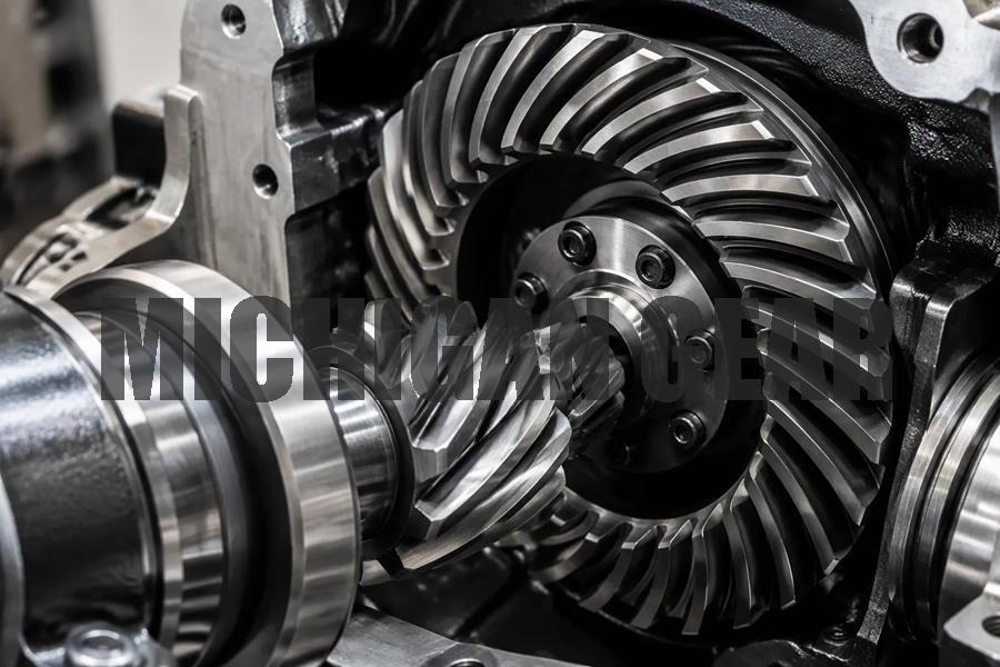
A spiral bevel gear has curved teeth on a conical surface. It performs torque transmission between intersecting shafts at 90 degrees while changing speed. This bevel gear stands apart from straight bevel gears because its teeth engage gradually. That yields smoother running and higher load capacity. Each bevel gear in a pair must match exactly.
For industrial power transmission, efficiency drives selection. Electromate reports about 94–98% efficiency for these gears. Gearbox Solutions adds that bevel gears commonly reach 97–99.5% efficiency. Such power transmission explains their popularity. Quiet transmission is another benefit.
You will explore terminology, gear types, manufacturing, design parameters, and mechanical power transmission.
Key Takeaways
●Spiral bevel gears have curved teeth that make them run smoother and quieter than straight bevel gears.
●You must replace spiral bevel gears in matched sets to avoid early failure and keep your equipment running well.
●Proper backlash and alignment are critical for spiral bevel gears to work efficiently and last a long time.
●Spiral bevel gears handle high speeds and heavy loads, making them perfect for industrial power transmission.
●Always choose the right bearings for spiral bevel gears because they create axial thrust that can damage your system.
Spiral Bevel Gear Basics and Terminology
What a Spiral Bevel Gear Is
A spiral bevel gear is a bevel gear with helical teeth cut along a conical surface. It transmits power between intersecting shafts, typically at 90 degrees. The curved tooth shape separates it from straight bevel gears. That curve produces gradual tooth engagement instead of sudden impact. You get smoother, quieter operation and higher load capacity as a result.
The principle of angular transmission relies on gear teeth cut along the surface of a cone. Bevel gears connect intersecting shafts using conical pitch surfaces. Their apexes meet at the shaft intersection point. As the gears rotate, mesh and unmesh cycles produce a contact pattern on the tooth flank. The size and position of this pattern affect gear life and power-transfer capacity. A no-load contact pattern should sit properly and should not extend to the tooth tip or heel.
Several standard terms describe spiral bevel gear geometry. You will encounter these in design documents and inspection reports.
| Term | Also known as | Definition |
|---|---|---|
| Pitch cone | Reference cone | Datum conical surface for design and processing; its apex coincides with the addendum and dedendum cones |
| Root cone | Dedendum cone | Conical surface containing all tooth dedenda; its apex coincides with the pitch cone apex |
| Face cone | Addendum cone | Conical surface containing all tooth addenda; its apex coincides with the pitch cone apex |
| Spiral angle | Helix angle (β) | Angle between the tangent to the helical tooth profile and the pitch-cone generatrix at the large end |
The spiral angle is a key parameter for meshing stability and load capacity. It shapes how the teeth contact during rotation.
Spiral Miter Gears and Mating
Spiral bevel gears are often paired with spiral bevel pinions. Together they create systems that change speed and torque in perpendicular shaft arrangements. This configuration supports right-angle power transmission across many industrial machines. The pinion drives the larger gear, and the ratio between tooth counts determines the speed change.
Mating requirements for these sets go beyond simple dimensions. You must match tooth geometry, set proper backlash, and align the components correctly. Three checks work together: backlash, contact pattern, and runout. Backlash is the clearance between mating tooth surfaces. It affects noise, heat, lubrication space, and assembly feel. Both insufficient and excessive backlash cause running problems. Contact pattern is the actual area where meshing gear teeth touch. It influences load distribution, wear, and service life. Runout is radial or axial deviation during rotation. Excessive runout distorts real backlash and contact results.
Do not approve a spiral bevel gear set by backlash alone. If runout is high, measured backlash may change as the gear rotates. If contact pattern is off, a correct backlash value on paper may still lead to poor load sharing in service. Gear alignment matters because small errors in shaft intersection or mounting distance shift the contact pattern. That shift causes noise, concentrated wear, or early failure.
The difference between helical vs bevel gears is worth noting here. Helical gears handle parallel shafts. Bevel gears handle intersecting shafts. Spiral bevel gears combine the gradual engagement of helical teeth with the angular capability of bevel geometry. That combination delivers smooth, quiet operation in right-angle drives and other power transmission systems.
Types of Bevel Gears and Spiral Variations
You will find four main types of bevel gears in mechanical drives. Each type has a distinct tooth form.
| Gear type | Distinguishing tooth form |
|---|---|
| Straight bevel | Straight teeth cut along the conical surface; teeth meet at the cone apex; simpler meshing; suitable for lower-speed machinery |
| Spiral bevel | Curved teeth that allow smoother meshing; quieter operation and better load distribution; used in high-speed applications |
| Hypoid | A variation of spiral bevel gears with offset shafts rather than intersecting axes; smoother and quieter than straight bevel gears |
| Zerol | A spiral bevel variant with a zero-degree spiral angle; avoids angled tooth contact; suitable for high-efficiency, low-noise applications |
The spiral tooth design separates the curved types from straight teeth. That curve produces gradual tooth engagement. The difference between helical vs bevel gears matters here. Helical gears serve parallel shafts. Bevel gears serve intersecting shafts.
Gleason versus Standard Spiral Bevel
Gleason-style spiral bevel gears use a circular arc tooth form with tapered tooth depth. Klingelnberg (Oerlikon) gears use uniform tooth depth with an epicycloid form. The two systems are not interchangeable. Tooling, machine setup, and tooth geometry are system-specific. Parts cut on one system will not mesh correctly with parts cut on the other.
Manufacturing these gears requires specialized equipment such as Gleason or Klingelnberg machines. That need raises complexity and cost. You should buy bevel gear pairs as matched sets. Replacing one gear without its partner causes premature failure from poor tooth contact. Precision alignment during installation is critical. Misalignment raises bearing loads and cuts efficiency. High precision ratings demand gear grinding that controls tooth geometry within microns.
Common Configuration Choices
Spiral bevel gears must be paired with opposite hands. The pinion is typically left-handed and the mating gear is right-handed. Hand direction, rotation direction, and driver or driven status together determine thrust force direction. The pinion thrust force can act in either direction. The bevel gear thrust force always pulls the gear out of mesh.
Gear orientation does not change torque capacity. It does affect the thrust forces introduced into the system. You must select thrust bearings carefully for any application with helix, spiral, or lead angle. This step protects the transmission and supports smooth power transmission in industrial equipment.
Manufacturing and Materials for Spiral Bevel Gears
How Spiral Bevel Teeth Are Cut
Producing curved teeth for a spiral bevel gear demands specialized gear-cutting machines. A bevel generator machine shapes the tooth flanks. Two methods dominate: face milling and face hobbing. Face milling indexes intermittently after each tooth slot. Face hobbing uses timed continuous indexing. This difference improves batch efficiency.
| Aspect | Face milling | Face hobbing |
|---|---|---|
| Indexing | Intermittent | Timed continuous |
| Cutter tooling | Cup-shaped cutter | Cutter head with blade groups |
| Lengthwise tooth curve | Circular arc | Extended epicycloid |
| Tooth depth | Tapered | Uniform |
The complexity surpasses straight bevel gear cutting. Teeth follow a spiral path on the pitch cone. A mating pinion and gear must share the same pitch, pressure angle, and spiral angle, but use opposite spiral directions. This bevel gear pair needs precise matching. A mismatched bevel gear will fail quickly. Grinding finishes the tooth flank after hardening. Most industrial bevel gears undergo grinding when quiet operation matters.
Materials and Heat Treatment
Alloy steels form the standard material choice for spiral bevel gears. Carburizing adds a hard, wear-resistant case. Most bevel gears in heavy equipment rely on carburized steel.
| Process | Typical steel | Surface hardness | Key benefit |
|---|---|---|---|
| Gas carburizing | Low-carbon alloy steels | Hard, wear-resistant case | Reliable for complex geometry |
| Induction hardening | Low-hardenability steels | Fine-grain martensite | Compressive residual stresses |
Post-heat-treatment steps improve fatigue strength. Shot peening induces residual compressive stress at tooth roots. Sub-zero treatment transforms retained austenite. These extra steps raise manufacturing cost. You must weigh that cost against smooth power transmission, high torque capacity, and quiet operation. The entire transmission benefits from the smooth mesh, but each bevel gear must handle axial thrust. Bearing selection must account for this force, especially when applying bevel gears in tight spaces.
Geometry and Design Parameters
Pitch, Pressure Angle, and Tooth Count
Pitch diameter defines gear size and tooth engagement geometry. It directly affects torque transmission and load capacity. Tooth count determines your gear ratio and mechanical advantage. You calculate the ratio by dividing the driven gear tooth count by the pinion tooth count. A 20-tooth pinion and a 60-tooth driven gear give you a 3:1 ratio. Designers avoid exact multiples of tooth counts. A hunting tooth combination such as 21/63 still yields 3:1 while promoting more even wear across the teeth.
Pressure angle affects the line of action and contact conditions. Typical values range from 14.5° to 20°. Your minimum pinion tooth count depends on this angle. At 14.5°, you need at least 32 teeth. At 20°, the minimum drops to 18. At 25°, you can use as few as 12. Too few teeth causes undercutting, which weakens the tooth base. A higher contact ratio means more teeth share the load at once. That produces smooth, quiet operation and longer gear life.
Backlash and Speed Ratio Limits
Backlash provides clearance for smooth meshing and prevents damage from tight contact. High-speed or high-precision applications call for a smaller backlash. Heavy-load applications may need a slightly larger gap to handle thermal expansion and prevent jamming. Backlash changes over time because of wear, so regular inspection and adjustment are required.
Single-stage bevel gearboxes achieve their highest efficiency because power passes through only one gear mesh. Their transmission ratios typically span from 1:1 up to 6:1. Gear size and torque capacity constrain this limit. Mismatched ratios cause premature equipment wear, excessive downtime, and energy inefficiency. Motors run outside their optimal range, which escalates to burnouts and accelerated tooth failure. Because ratio alone does not define the gearset, angle selection, tooth form, setup, and contact control all change how the gears actually run.
Operation and Industrial Transmission Applications
Pinion-Driven versus Gear-Driven Behavior
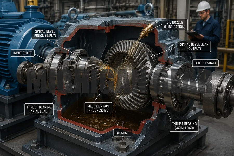
The pinion usually drives the larger gear in a spiral bevel gear set. This arrangement affects how load distributes across the tooth surface. When the pinion turns the gear, the contact pattern shifts along the tooth length. You get progressive loading instead of sudden impact. That behavior supports smooth power transmission and extends gear life.
Axial force in spiral bevel gears changes with rotational direction. The curved tooth design creates this effect. The pinion thrust force can act in either direction depending on rotation. The gear thrust force always pulls the gear out of mesh. You must account for this force when you select bearings and lubrication. Thrust bearings handle the axial load. Proper lubrication keeps the contact surfaces cool and reduces wear. Ignoring axial force leads to bearing failure and poor performance in industrial power transmission systems.
Advantages and Real-World Use Cases
Spiral bevel gears offer clear benefits over straight bevel gears. The curved teeth engage gradually. This gradual tooth engagement produces smooth, quiet operation. Spiral bevel gears use line contact instead of point contact. That increases torque capacity and load-bearing ability. They maintain better stability at high speeds. You also get higher efficiency with less friction and heat.
These gears carry some disadvantages. Axial forces demand robust bearings. Overheating can occur under poor lubrication or heavy continuous duty. Manufacturing complexity is higher than straight bevel gears. You need specialized machines and matched gear sets.
| Attribute | Straight Bevel Gear | Spiral Bevel Gear |
|---|---|---|
| Tooth line | Straight | Curved / spiral |
| Meshing style | Relatively direct | Progressive meshing |
| Running smoothness | General | Usually better |
| High-speed application | Relatively limited | More suitable |
| Noise control | Suitable when noise requirements are not high | Better for low-noise requirements |
| Manufacturing complexity | Lower | Higher |
| Common applications | Low speed, medium load | Medium to high speed, higher load |
You will find spiral bevel gears in many demanding settings. Automotive differentials adjust speed differences between left and right axles during turns. Heavy equipment such as excavators uses them in slewing mechanisms and track drives. Industrial right-angle gearboxes power cooling towers, printing presses, and steel mill rolling mills. Wind turbines rely on them to handle force between slow blades and high-speed generators. These bevel gears also serve in conveyor systems, packaging machinery, and machine tool accessories. Each application needs specific torque, speed, and noise performance. You should match the bevel gear to your load and operating conditions. A generic choice will not deliver the smooth, quiet operation or the torque transmission your mechanical power transmission system requires.
Spiral bevel gear sets deliver right-angle torque transmission. Rely on spiral bevel gears for smooth, quiet industrial power transmission. Choose bevel gear type, material, heat treatment, pitch, pressure angle, backlash, and ratio limits. Every bevel gear creates axial thrust; select bearings for that force. Efficiency needs matched pairs and proper lubrication. Avoid a generic bevel gear. Match bevel gears to exact load, speed, and noise targets. The right bevel gear saves downtime. Consider the spiral bevel tooth shape. Always align bevel gears carefully. Always check bevel gears for wear. Replace bevel gears as matched sets. This design stays vital in heavy drivetrains.
FAQ
What makes a spiral bevel gear different from a straight bevel gear?
A spiral bevel gear carries curved teeth on a conical surface. Straight bevel gears use straight teeth. The curve produces gradual tooth engagement instead of sudden impact. You get smoother, quieter running and higher load capacity. These bevel gears also handle high speeds better than straight designs.
Why must you replace bevel gears as matched sets?
Mating bevel gears share pitch, pressure angle, and spiral angle. Their spiral directions run opposite. A mismatched bevel gear will fail quickly. You should always buy bevel gear pairs together. Replacing one gear alone causes poor tooth contact and premature failure.
What backlash value should you target for a spiral bevel gear?
High-speed or high-precision work calls for a smaller backlash. Heavy-load applications may need a slightly larger gap. Backlash changes with wear, so inspect and adjust it regularly.
How do you select bearings for spiral bevel gears?
Every spiral bevel gear creates axial thrust. The pinion thrust force can act in either direction. The gear thrust force always pulls the gear out of mesh. You must choose thrust bearings that handle this load. Proper lubrication also keeps contact surfaces cool.
Where do you find spiral bevel gears in industry?
Automotive differentials use them to adjust axle speed during turns. Heavy equipment relies on them in slewing mechanisms and track drives. Wind turbines use them between slow blades and high-speed generators. Conveyor systems, printing presses, and steel mill rolling mills also depend on them.
Post time: Oct-08-2026