


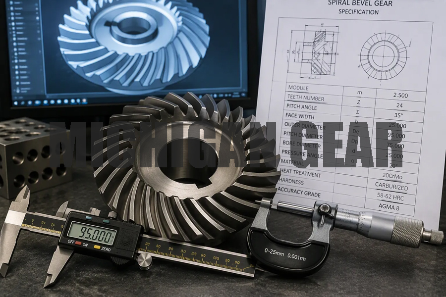
Ordering a spiral bevel gear without a clear checklist leads to costly mistakes. You need a full set of specifications that covers basic parameters, geometry, material, quality, and mounting details. Each category protects the part’s fit, strength, and service life.
Your technical drawing is the best way to communicate. Include mounting distance targets, backlash windows, certificates with traceable heat numbers, and heat treatment reports on that drawing. A complete specification shortens lead times. Remember to add duty-cycle inputs like torque range, speed, direction changes, and lubrication type.
This checklist keeps every requirement visible to your supplier. Clear documentation stops manufacturing errors before they start.
Key Takeaways
- Give a full list of specs to avoid expensive errors and delays.
- Add basic details like module, teeth, pressure angle, and gear ratio.
- Give the gear’s size details, like pitch diameter, face width, spiral angle, and hand of spiral.
- List the material grade, heat treatment, and quality standards such as backlash and mounting distance.
- Use a detailed technical drawing to clearly share all requirements with your supplier.
Key Specifications for a Spiral Bevel Gear
Module, Teeth, and Pressure Angle
The module sets the tooth size of your spiral bevel gear. A larger module means bigger, stronger teeth. You choose the module based on the torque your application needs to handle.
The number of teeth on both the gear and pinion shapes the tooth profile. This count changes the gear ratio and how smoothly the gears run. You must give the tooth count for the gear and the mating pinion. A matched bevel gear set will mesh properly.
The pressure angle plays a very important role in load capacity. A larger pressure angle makes the tooth stronger at its root. It also makes the radial force on the bearings larger. Most spiral bevel gear designs use a standard pressure angle. You should check this value with your supplier. Together, the pressure angle, module, and tooth count define the basic tooth geometry. These three values are the foundation of any bevel gear design.
Determining the Required Gear Ratio
The required gear ratio tells you how input speed relates to output speed. You can calculate it easily with a simple formula: gear ratio equals input speed divided by output speed. The gear ratio also equals the driven gear teeth divided by the driving gear teeth. If the ratio is greater than 1, then you have a reduction drive. If it is less than 1, then you have a speed-increasing drive.
A higher ratio boosts torque output. That fits machines like crushers and haul trucks that handle heavy loads. A lower ratio gives higher speed. That helps conveyors and drilling rigs that need fast movement. The ratio affects both torque delivery and transmission efficiency.
For spiral bevel gears, the speed ratio range usually falls between 1:1 and 6:1. Single-stage bevel gears have a similar limit for right-angle applications. Bevel gears achieve an efficiency of 92 to 97 percent per stage. Spiral bevel gears reach 94 to 98 percent. These numbers show that a good bevel gear set loses little power.
Efficiency by Gear Type:
Gear Type Efficiency Per Stage Best Applications Bevel/Spiral Bevel 94-98% Right-angle drives, moderate ratios
You must write the required gear ratio on your drawing. This one number sets the tooth count for both gears. It also decides the housing size and bearing loads. A wrong ratio makes the entire assembly fail to meet performance targets. Always double-check your ratio calculation before you place an order.
Defining the Gear’s Geometry and Rotation
Pitch Diameter, Face Width, and Spiral Angle
Pitch diameter and face width are the main measurements that decide if your gear fits and how much load it can carry. You measure pitch diameter at the back of the tooth. This value directly changes how much wear load your gear can handle. A larger pitch diameter raises the allowed tangential load.
Face width runs from the heel to the toe of each tooth. This measurement controls torque capacity in a direct, linear way. If you increase face width by 20 percent, torque capacity rises by 20 percent. But bevel gear geometry limits face width. Keep it below one-third of the cone distance or ten times the module, whichever is smaller.
The spiral angle sets the way the teeth curve across the face. This angle balances load sharing and thrust force. A higher spiral angle raises the contact ratio and makes operation smoother and quieter. It also raises axial thrust loads on the bearings. You must confirm the spiral angle with your supplier, since it changes the contact pattern across the tooth surface.
Hand of Spiral and Direction of Rotation
The hand of the spiral tells you which way the teeth lean. A right-hand spiral bevel gear has teeth that lean clockwise from the axial plane when you look at the gear face. A left-hand gear leans counterclockwise. This matters because a spiral bevel gear and pinion must always be of opposite hand. A matched bevel gear set only meshes correctly when one member is left-hand and the other is right-hand.
Direction of rotation works together with the hand of the spiral. The pinion thrust direction depends on the direction of rotation and which gear drives. The gear thrust always pulls the gear out of mesh. Torque capacity does not change with left or right orientation. But the thrust forces that enter your system do change. You must specify both the hand and the rotation direction on your drawing. This step ensures proper meshing and prevents early failure.
A right-hand spiral bevel gear has its outer tooth half leaning clockwise from the axial plane through the tooth midpoint, as seen by someone looking at the gear face. A left-hand gear leans counterclockwise.
Material and Heat Treatment Requirements
SCM415 alloy steel is a common choice for spiral bevel gears used in heavy service. It has good core toughness and works well with case hardening. You should list the core hardness in your material specification. A ductile core helps prevent brittle fracture under shock loads.
The core supports the hard outer case and resists bending fatigue and impact. Write down the material grade, the core hardness range, and the alloy limits. The base material must fit the hardening process you plan to use. Confirm that your chosen material can reach the needed core hardness after the full heat treatment cycle.
Material Selection and Core Hardness
Heat Treatment and Surface Hardness
Most spiral bevel gears use carburizing as their main heat treatment. Gas carburizing adds carbon to the surface layer at high temperature. The part is then quenched and tempered.
Hypoid and bevel gears, spiral bevel automotive gears, commercial pinions, and noncircular gears were rarely induction hardened because of their complex shapes. So they were usually carburized.
Carburizing creates a hard outer case while keeping the core tough. The table below shows the usual surface hardness after this heat treatment:
| Parameter | Typical Range |
|---|---|
| Surface hardness (gas carburized gears) | 58–63 HRC |
| Case-region carbon content | 0.7–1.0% C |
The useful case depth for most industrial gear applications falls in this range:
- 0.020 inch to over 0.250 inch
Choose a case depth that matches your contact stress. The case must be deep enough so the material strength is greater than the subsurface shear stress from surface contact.
This heat treatment gives several benefits. Carburizing transforms the surface material into a wear-resistant barrier. Compressive residual stresses improve fatigue strength. The ductile core absorbs shock loads, and the hard surface resists deformation.
Your heat treatment specification must list surface hardness, case depth, and core hardness. State the acceptable range. The supplier should provide a test report after the final heat treatment. The hard case protects the material underneath from contact fatigue. This report proves that the material met every requirement.
Quality Standards, Backlash, and Mounting
Gear Grade, Tooth Finish, and Backlash
Gear quality controls how smoothly your spiral bevel gear runs. Put a gear grade on your technical drawing. The AGMA quality number is often used for bevel gears. Tighter tolerances for tooth profile, pitch, and runout come with a higher grade. AGMA Class 8 or 9 balances precision and cost for most industrial drives. Precision applications may need Class 10 or higher.
Tooth finish also affects gear quality. Cut teeth work fine for general power transmission. Ground teeth give a better surface finish and tighter tolerances. Grinding removes heat treatment distortion and helps contact pattern development. State whether you need cut or ground teeth. Base this choice on your speed and noise needs.
Backlash is the gap between mating tooth flanks. Tell your supplier your backlash requirement clearly. Too little backlash causes binding and heat. Too much backlash causes noise and impact loads. Put backlash as a range on your drawing. A normal backlash range for spiral bevel gears depends on module and application. Your supplier can suggest a value that gives smooth operation and low noise.
Mounting Distance and Bore Details
Mounting distance sets where your gear sits compared to its mating pinion. This dimension is vital for good contact pattern development. Check mounting distance at a normal operating load with preloaded bearings. The mounting distance tolerance is tight. Think about these points:
- Even a small axes misalignment can cause a major contact pattern change.
- An offset error changes the contact pattern by a similar amount.
- The contact area should cover the whole flank surface with no edge contact when the nominal load rating is reached.
The mounting distance tolerance for bevel gears is usually stated directly on the design drawing. As long as the measured mounting distance stays inside the set tolerance range, the transmission system’s performance is not changed much.
Bore details finish your mounting specification. Give the bore diameter, keyway dimensions, and all tolerances. Say whether the bore needs a press fit, slip fit, or interference fit. Include the bore length and any chamfers or fillets. These dimensions make sure your gear mounts correctly on the shaft.
Providing Your Technical Drawing and Manufacturing Drawing
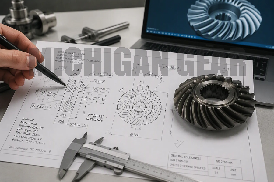
A full technical drawing is your best way to talk to the supplier. Put all specifications on it: dimensions, tolerances, material, heat treatment, and quality grade. Without this document, the supplier has to guess.
Essential Information for Your Drawings
Your manufacturing drawing must list the basic gear data. This includes tooth count, module, pressure angle, face width, and required gear ratio. Then add geometric and mating data. Include mating gear number, shaft angle, hand of spiral, and mounting distance.
The table below lists the drawing requirements that protect function:
| Requirement | Purpose |
|---|---|
| Reference datum | Master surface for setup and final inspection |
| Bore / shaft journal | Primary locating surface; IT7 tolerance |
| Mounting distance | Axial position of gear vs. shaft intersection |
| Face cone angle | Preserves face width and tooth geometry |
State manufacturing tolerances for each feature. The drawing needs geometric tolerances for runout, back-face perpendicularity, and bore concentricity. For moderate-duty gears, use Ra ≤ 1.6 µm on tooth flanks.
The material grade matters. Write the steel grade, such as 20CrMnTi. State the thermal process: carburize, quench, temper. Set surface hardness 58–64 HRC, core hardness 33–48 HRC, case depth 1.2–1.6 mm at 550 HV. Note shot peening 30–50 minutes if required.
The base material and the heat treatment path decide how long the gear lasts. The gear ratio changes tooth counts and housing loads. A higher ratio raises output torque. A lower ratio gives output speed. Your ratio choice affects every mounting dimension. If the ratio is wrong, the gear set will not meet its speed target. Most right-angle drives use a reduction ratio from 1 to 6. During quotation, confirm the ratio matches the drawing.
Inspection and Supplier Selection Criteria
Tell the supplier what inspection you need for acceptance. A coordinate measuring machine maps the tooth working surface. Then it compares the measured data to the target values stored in the machine. This automatic method replaces subjective tooth patterning and cuts inspection time. After assembly, do a contact pattern check. Keep the contact pattern centered when contact starts.
Put a quality class on every drawing. AGMA Class 8 or 9 works for general-purpose gears. Choose Class 10 or higher for precision machine-tool applications. Ask for a material report and a hardness report. A contact pattern report proves the tooth flanks match your drawing. That pattern depends on mounting distance, so keep the gear ratio clear. A ratio of 1 means no speed change.
Your manufacturing drawing finishes the process when you choose a supplier. Ask for a sample CMM report, surface roughness measurement, and material certificate from a similar job. Check in-house inspection, current ISO certification, and material traceability. During quotation, review the order, gear parameters, material, thermal process, quantity plan, and application details. Before shipment, agree on material evidence and hardness results.
One caution: if a supplier cannot provide material certifications, or gives vague answers about gear-cutting equipment, move on. NADCAP accreditation for thermal processing is strong proof that the thermal cycle matches your specifications. This process prevents costly surprises later. Choose a partner who proves quality at every step.
Begin with the basic details: module, teeth, pressure angle, and gear ratio. Then set the shape: pitch diameter, face width, spiral angle, hand, and rotation. Next, list the material grade, core hardness, and case depth. Add the quality grade, backlash, and mounting distance. End with a full manufacturing drawing.
A complete specification sheet prevents mistakes and shortens delays. It makes sure your spiral bevel gear works well. Use this checklist for every order. Confirm the gear ratio, the speed ratio, and the torque ratio. Check every material callout, every material certificate, and every material test report. Verify the reduction ratio and the drive ratio. Review the overall ratio and the material properties. Check the ratio. Your supplier will thank you.
FAQ
What is the most common spiral angle for a spiral bevel gear?
This angle balances load sharing and thrust force. A higher angle makes operation smoother and quieter. It also raises axial thrust loads on your bearings. Always confirm the spiral angle with your supplier.
Why must the gear and pinion have opposite hands?
A spiral bevel gear and pinion must always be of opposite hand. A matched set only meshes correctly when one member is left-hand and the other is right-hand. You must specify both the hand and the rotation direction on your drawing to prevent early failure.
What surface hardness should I expect after carburizing?
Gas carburized gears typically reach 58–63 HRC at the surface. The case-region carbon content usually falls between 0.7 and 1.0 percent. Your heat treatment specification must list surface hardness, case depth, and core hardness. The supplier should provide a test report after the final heat treatment.
How do I communicate backlash requirements to my supplier?
Put backlash as a range on your drawing. Too little backlash causes binding and heat. Too much backlash causes noise and impact loads. Your supplier can suggest a value that gives smooth operation and low noise for your module and application.
What should I include on my manufacturing drawing?
List tooth count, module, pressure angle, face width, and gear ratio. Add mating gear number, shaft angle, hand of spiral, and mounting distance. Include material grade, heat treatment details, and quality grade. State geometric tolerances for runout and bore concentricity. A complete drawing prevents manufacturing errors.
Post time: Oct-13-2026