


Load and strength needs set the module, and you should pick it from a standard series. Speed and torque requirements set the ratio, within size limits. Smoothness, strength, and undercut limits set the tooth count. You must balance all three together.
These practical rules guide your specification of a spiral bevel gear. Industrial spiral bevel gears commonly use a module range of M2 to M15, or 2 to 10 mm in many high-speed, heavy-load systems. Typical gear ratios for spiral bevel gears run from 1 to 4, with a maximum limit near 8. A 48-tooth wheel driving a 12-tooth pinion gives a 4:1 ratio. Choose tooth counts and teeth geometry as one matched set, because each choice reshapes the others.
Key Takeaways
- Start with the load to pick the module, then choose a standard size for strength and tooling.
- Set the gear ratio from speed and torque needs, keeping it under 10:1 for one stage.
- Choose tooth count for smooth running and strength, and check undercut limits for your gear type.
- Treat module, ratio, and tooth count as one system because changing one affects the others.
- Consult a gear expert for high-load or precision designs to avoid costly errors.
Module Selection for a Spiral Bevel Gear
The module of a gear describes tooth size. This single value shapes four things at once: bending strength, tooth count, contact ratio, and running smoothness. A larger module means chunkier teeth that carry more load. A smaller module packs more teeth onto the same pitch cone and runs more quietly. You cannot optimize one without shifting the others, so treat module as the anchor of your design.
Load Capacity and Bending Strength
Start with the load. Torque at the pinion, shock loading, and duty cycle all push you toward a larger module. Thin teeth bend and break under high torque, so bending strength sets the floor for your tooth size. A spiral bevel gear in a heavy-load system typically needs a module between M2 and M15, and many high-speed, heavy-load drives land in the 2 to 10 mm band. Light instrument drives sit well below that range.
You can estimate the module before you commit to a full design. Estimate the pitch diameter at the large end of the tooth, then divide by the number of teeth. The result gives you a working module to check against your strength calculations. Treat this as a starting point, not a final answer. Face width, material, and tooth system still shape the real load capacity of the pair.
Standard Module Series
Cutters, hobs, and inspection gauges come in standard sizes. Choosing a standard module keeps your spiral bevel gear interchangeable with off-the-shelf tooling and shortens lead times. Custom modules force custom cutters, and that raises cost and risk.
Standard series exist for exactly this reason. Two gears mesh cleanly only when they share the same pitch or module, so the series gives every supplier a common language. Pick the nearest standard value above your calculated minimum. Rounding up adds a small strength margin at almost no cost. Rounding down saves space but eats into your safety factor.
Keep the gear tooth pitch consistent across the mating pair. A pinion and wheel with mismatched module will not run. Verify the module against the standard series at the same time you fix the pitch cone angle and face width. These choices interact, and a late change to one forces rework on the others.
Gear Ratio: Speed and Torque Balance
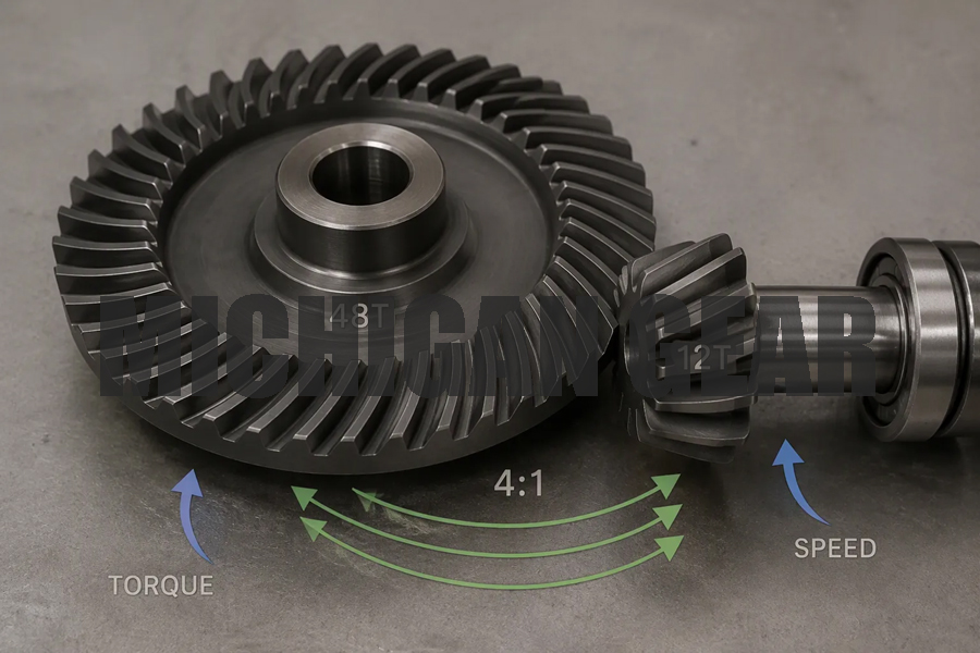
The gear ratio links the input shaft to the output shaft through the tooth counts. Divide the driven gear teeth by the pinion teeth and you have your ratio. A 48-tooth wheel driven by a 12-tooth pinion gives 48 divided by 12, or 4:1. The pinion turns four times for every single turn of the wheel. That number is your speed ratio, and it holds without slip because the teeth mesh by form, not by friction.
Speed, Torque, and Efficiency
Ratio direction decides what you get at the output. A higher ratio slows the output and multiplies torque, which suits mining, metallurgy, cranes, and ship propulsion. A lower ratio keeps output speed close to input speed and changes direction with little torque shift, which suits 90-degree direction changes and synchronization duties. Match the ratio to the working machine, not to a catalog preference.
| Gear Ratio Direction | Effect on Speed | Effect on Torque | Typical Use |
|---|---|---|---|
| Higher gear ratio | Reduces output speed | Increases torque | Heavy load carrying, such as mining and cranes |
| Lower gear ratio | Faster output rotation | Reduced torque | Speed matching and direction changes |
Efficiency stays high across this range. Spiral bevel gear sets typically deliver 94% to 98%, though startup losses, lubrication, and mounting orientation all pull at that figure. A speed increaser works like a reducer run backward, with the lower-tooth-count gear as the output. Helicopter main rotor drives use this arrangement, with power take-off pinion-to-ring ratios of 4 to 6 acting as speed increasers.
Hypoid gears can achieve higher reduction ratios than spiral bevel gears, but their sliding action along the teeth reduces mechanical efficiency, with energy lost as heat in the gear surfaces and lubricating fluid.
Size Limits and Ratio Caps
Single-stage spiral bevel gear sets commonly ship with gear ratios ranging from 1:1 up to 6:1. Push past that and you need multiple stages. Each added stage costs you efficiency, adds backlash, grows size and weight, and lowers reliability. As a practical rule, cap a bevel gear set at 6:1 reduction and hold any step-up or step-down step to 5:1. Ratios ranging from 2:1 to 4:1 cover most general industrial drives and keep you well inside those limits.
The tooth-count ratio gives the ideal speed ratio, and nothing more. A real matched gear set still needs module, face width, tooth system and material fixed before anyone can cut it. The module sets tooth size, the face width sets load-bearing area, the tooth system sets the spiral angle and profile, and the material sets allowable stress. Change one and the others shift. Verify the pitch cone angle and the face width against your chosen ratio before you release the drawing.
Tooth Count and Undercut Limits
Tooth count decides how smoothly the pair runs and how strong each tooth stays. You set the pinion tooth count and the driven tooth count together, because their sum and split shape the whole mesh. A spiral bevel gear uses curved teeth, and that curve changes how many teeth share the load at any instant.
Contact Ratio and Smoothness
Contact ratio measures how many tooth pairs mesh at the same moment. A spiral tooth line keeps the next pair engaged before the last one leaves, so load passes gradually instead of jumping. Typical designs land between 1.8 and 2.5, and most run at 2 or above. Drop below 1 and you get moments with no meshing pair at all, which brings hard impact, vibration, and noise.
Higher contact ratio buys smoother meshing, lower noise, and more even load sharing. It also costs you. More sliding between surfaces raises friction loss, grows the package, and demands tighter precision and higher manufacturing cost. Contact ratio is one factor among many. Tooth profile and lead deviations, microgeometry, runout, backlash, surface finish, alignment, bearings, lubrication, speed, and load all shape real smoothness. On a spiral bevel gear, contact happens on curved three-dimensional surfaces, so you must also check the spiral angle, the pitch cone, the contact pattern, and the mounting position.
Minimum Tooth Count Rules
The classic 17-tooth rule guards involute gears against undercutting. Cut fewer than 17 teeth on a standard involute profile and the cutter digs into the tooth root, weakening the base. That rule is a guideline, and its applicability to spiral bevel gears may vary. The curved tooth form and the cone geometry shift the undercut threshold, so confirm the limit for your specific tooth system rather than applying 17 blindly.
Small pinion teeth raise the tooth-count ratio for a given wheel size, which helps when you need reduction in a tight envelope. They also thin the root and cut bending strength. Balance the two by raising the module when you shrink the pinion, and check the result against your load case. Keep the gear tooth pitch matched across the pair, and verify the number of teeth against the pitch diameter at the large end before you finalize the drawing.
Combining Module, Ratio, and Tooth Count
You cannot lock one parameter and walk away. The module, the tooth counts, the contact ratio, and running smoothness all move together. Change the module and the pitch diameter shifts, which reshapes the ratio for a fixed tooth count. Shrink the pinion and bending strength drops, so you raise the module to compensate. Treat the design as a loop, not a checklist.
Iterative Cross-Checks
Run the loop in a fixed order so nothing drifts. Start with power and operating data: transmitted power, rotation speed, gear type, material, and load type. Add the ratio or tooth counts, the shaft axis angle, the offset, the toothing width, and the spiral angle. Define the tooth profile, then pick the calculation method that matches your toothing type. Enter the geometry or run the iteration, and check the output on the graphic display. Load the result into CAD or export data for a precision 3D model when the numbers settle.
Cross-check each value against its rule as you go. Keep the wheel pitch diameter above your preliminary reference value and the face width below its reference value. Hold the mean spiral angle above the level needed for a mesh coefficient of 2.0, inside the permitted range. Cap any hypoid offset at 25% of the wheel pitch diameter. Set backlash from the suggested minimum, scaled to the module per ISO accuracy grade. To land an exact module, enter the target value, recompute the pitch diameter, and run the iteration again.
Software shortens this loop. Gleason CAGE for Windows pairs design with tooth contact analysis and loaded tooth contact analysis, and it handles both face hobbing and face milling. Other packages support the same iterative work.
When to Consult an Expert
Some applications sit outside catalog territory. Call in a gear expert when you need help with high-load industrial drives, tooth geometry and contact pattern optimization, noise reduction, load capacity gains, or a design problem that will not resolve. A spiral bevel gear drive is often a precisely engineered machine, not a commodity part.
Start with the vendor's catalog or website for a preliminary specification. Contact the vendor or distributor when your requirements look unusual. Choose one willing to work closely with you, because that partnership cuts cost and design time, simplifies engineering, and lowers risk.
Start with load. Load sets the module, so pick a standard value. Next, set the ratio from speed and torque needs, staying within 6:1 reduction and 5:1 per step. Then choose tooth count for smoothness and strength, and respect undercut guidelines.
Treat these three as one system. Small errors compound quickly. A change to one value shifts the pitch cone and the speed relationship for a fixed number of teeth. Verify all values together, never one at a time. For complex, high-load, or precision-critical bevel gears, consult a gear expert or manufacturer. Their review protects your tooth geometry and your schedule.
FAQ
How do you estimate the module before a full design?
Estimate the pitch diameter at the large end of the tooth, then divide by the number of teeth. That gives you a working module to check against your strength calculations. Treat it as a starting point, not a final answer.
Can you exceed a 6:1 reduction in one stage?
No. Cap a single-stage bevel gear set at 6:1 reduction and hold any step-up or step-down step to 5:1. Push past that and you need multiple stages. Each added stage costs efficiency, adds backlash, and grows size and weight.
Why does a 48-tooth wheel with a 12-tooth pinion give 4:1?
Divide the driven gear teeth by the pinion teeth. 48 divided by 12 equals 4. The pinion turns four times for every single turn of the wheel. That ratio holds without slip because the teeth mesh by form, not friction.
Does the 17-tooth rule apply to spiral bevel gears?
The 17-tooth rule guards involute gears against undercutting. Its applicability to spiral bevel gears may vary. The curved tooth form and the cone geometry shift the undercut threshold. Confirm the limit for your specific tooth system rather than applying 17 blindly.
What contact ratio should you target?
Typical designs land between 1.8 and 2.5, and most run at 2 or above. Drop below 1 and you get moments with no meshing pair at all. That brings hard impact, vibration, and noise. Check the pitch cone and contact pattern too.
Post time: Oct-26-2026