


Quick Answer
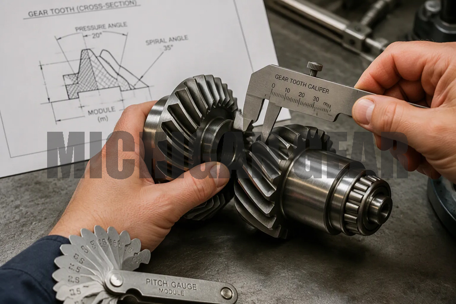
Sourcing custom spiral bevel gears for OEM gearbox applications requires matching a manufacturer’s machining envelope to your gear’s geometry, then verifying inspection capability and matched-set testing before production. The critical first step is providing a complete technical package: module, tooth count, pitch diameter, face width, spiral angle, material, heat treatment, and accuracy grade (DIN, AGMA, or ISO). A manufacturer equipped with five-axis bevel gear grinding centers and CMM inspection can hold DIN 5 accuracy on custom geometries . The target supplier’s Gleason FT16000 five-axis machining center and Zeiss/Klingelnberg inspection equipment indicate capability for complex spiral bevel geometries, but buyers must confirm that the specific inspection protocol includes contact pattern verification on the assembled pair, not just individual tooth geometry checks .
Key Takeaways
●A complete drawing is the non-negotiable starting point. Module, tooth count, face width, spiral angle, material, heat treatment, and accuracy grade must all be specified; missing any one of these forces the manufacturer to guess .
●Matched-set inspection matters for spiral bevel gears. Two individually acceptable gears can still produce unacceptable noise or contact patterns when assembled; specify backlash and contact pattern requirements upfront .
●Accuracy grade drives cost and lead time. DIN 5 requires grinding after heat treatment; DIN 8 may be achievable with lapping or milling, shortening lead time but limiting precision .
●Gleason and Klingelnberg are the reference systems. A manufacturer’s machine tool brand tells you which tooth form system they can produce and which design standards apply .
●The target supplier’s stated capability includes any module, any tooth count, and DIN 5 accuracy, supported by a Gleason FT16000 five-axis center and a metrology lab with Zeiss and Klingelnberg instruments.
What a Custom Spiral Bevel Gear Specification Package Must Contain
A spiral bevel gear is not a catalog item. Every geometry parameter interacts with every other parameter, and the manufacturing process must be planned around the complete specification. The most common sourcing failure is an incomplete inquiry that leads to a quotation for the wrong gear.
The Essential Drawing Elements
| Parameter | Why It Matters | Typical Range / Specification |
|---|---|---|
| Module | Sets tooth size and bending strength | M2–M15 for heavy industrial; M0.5–M4 for precision instruments |
| Tooth count | Determines ratio and undercut risk | Pinion typically ≥9 teeth to avoid undercut |
| Pitch diameter | Defines gear size and housing envelope | Must be specified at the large end of the tooth |
| Face width | Load-bearing area; affects contact pattern | Typically 0.25–0.3 × cone distance |
| Spiral angle | Controls overlap ratio and smoothness | 17°–35° common; up to 45° possible |
| Shaft angle | Defines the 90° (or other) intersection | Most commonly 90° |
| Material | Strength, hardenability, cost | 20CrMnTi, 42CrMo, 9310, case carburizing grades |
| Heat treatment | Surface hardness and core toughness | Carburize + quench to 58–62 HRC; or nitride for lower distortion |
| Accuracy grade | Tooth spacing, profile, and lead tolerance | DIN 5–8; AGMA 10–13 equivalent |
When No Drawing Exists
For replacement or legacy gearbox applications, the original drawing may be unavailable. In this case, the supplier must offer reverse engineering capability: measuring the existing gear pair, determining the tooth form system (Gleason, Klingelnberg, or Oerlikon), and generating a manufacturing drawing for approval before cutting metal . A supplier that cannot perform this step is limited to producing gears from customer-supplied drawings only—a significant constraint for maintenance and repair applications.
Manufacturing Method Determines Achievable Accuracy
Spiral bevel gears can be produced by milling, hobbing, or grinding. The method chosen determines the achievable accuracy grade, the need for heat treatment distortion compensation, and the unit cost.
Milling and Hobbing vs. Grinding
| Process | Typical Accuracy | Post-Heat Treatment | Best For |
|---|---|---|---|
| Face milling (intermittent) | DIN 7–8 | Lapping after heat treatment | Moderate-volume industrial gears, non-critical noise applications |
| Hobbing (continuous) | DIN 7–8 | Lapping or no correction | High-volume automotive-style production |
| Formate grinding | DIN 5–6 | Ground after heat treatment | Precision gearboxes, low noise requirements |
| Generating grinding | DIN 5 | Ground after heat treatment | High-precision, low-volume, custom geometries |
The target supplier’s stated DIN 5 accuracy and use of a Gleason FT16000 five-axis machining center indicate a grinding-based process. Grinding after heat treatment corrects distortion from carburizing and quenching, which is why it is the standard process for precision gearbox applications. A supplier offering only milling and lapping cannot reliably hold DIN 5 on a hardened gear.
The Heat Treatment Distortion Problem
Carburizing and quenching at 58–62 HRC introduces distortion that must be corrected by grinding or lapping. A gear cut to final dimensions before heat treatment will not meet DIN 5 after quenching. The production sequence must include green machining (leaving stock) → heat treatment → finish grinding. The target supplier’s stated production flow—rough cutting, turning, quenching and tempering, gear milling, heat treatment, gear grinding, testing—reflects this sequence.
Inspection: What to Verify Beyond Dimensional Checks
The target supplier lists an impressive metrology inventory: Brown & Sharpe, Hexagon CMM, Zeiss CMM, Mahr roughness/contour, and Klingelnberg gear measuring instruments. These tools confirm that the supplier can measure gear geometry. The question for the buyer is what is measured, and against what acceptance criteria.
Individual Gear Inspection
For each gear in the pair, the following characteristics should be documented:
●Tooth profile and lead deviation (Klingelnberg or equivalent gear checker)
●Tooth spacing (pitch) variation
●Runout (radial and axial)
●Hardness (case depth and surface hardness)
●Material certification (mill certificate for the steel grade)
●Surface finish on tooth flanks
Matched-Set Inspection: The Critical Addition
Spiral bevel gears are manufactured as a pair. Individual dimensional compliance does not guarantee acceptable mesh. The buyer should specify that the supplier will perform matched-set inspection on the assembled gear and pinion:
●Backlash measurement under the specified mounting distance
●Contact pattern check (tooth bearing) under light load
●Pair identification (serial number marked on both members) to maintain the matched relationship through shipping and installation
For OEM gearbox applications where noise, vibration, and durability are acceptance criteria, matched-set inspection is not optional. A supplier that inspects only individual gears is delivering components, not a functional gear set.
The Target Supplier’s Capability Profile: What to Verify
The target manufacturer states the following capabilities. Each claim maps to a verification action for the buyer.
| Supplier Claim | What It Means | Buyer Verification Action |
|---|---|---|
| Any module, any tooth count | No catalog limitation; custom geometry accepted | Confirm the drawing falls within the machine’s physical envelope (workpiece diameter, face width) |
| DIN 5 accuracy | Precision grinding capability | Request a sample inspection report for a comparable gear showing DIN 5 tooth profile/lead results |
| Gleason FT16000 five-axis center | Large-capacity bevel gear cutting/grinding | Confirm the machine is operational and assigned to the project; request photos of the setup |
| Zeiss/Klingelnberg inspection | Full geometry and roughness measurement | Request the specific inspection plan for the gear; confirm contact pattern is included |
| 200,000 m² production area | Manufacturing scale | Factory video audit confirms production floor and equipment |
Questions to Ask Before Releasing the Drawing
1.Which tooth form system will be used—Gleason, Klingelnberg, or Oerlikon? The system determines the cutting/grinding method and the design calculation basis.
2.What is the inspection plan for the specific gear? Request the list of characteristics to be measured, the instruments used, and the acceptance criteria for each.
3.Will matched-set contact pattern be verified and documented? If not, the gearbox assembler assumes the risk of unacceptable noise or wear.
4.What is the lead time for a first article sample at the specified accuracy grade? Standard production timelines for custom ground spiral bevel gears typically run 4–8 weeks depending on complexity and material availability.
FAQ
What is the minimum information needed to quote a custom spiral bevel gear?
A complete drawing with module, tooth count, pitch diameter, face width, spiral angle, shaft angle, material, heat treatment, and accuracy grade. If no drawing exists, the supplier must be able to reverse-engineer from a sample or gearbox dimensions. A quotation based only on outside diameter and tooth count is unreliable .
What accuracy grade is realistic for a custom spiral bevel gear from a Chinese manufacturer?
DIN 5 is achievable with grinding-capable suppliers. The target manufacturer states DIN 5 as its highest grade, supported by Gleason and Klingelnberg inspection equipment. DIN 6–7 is more common for general industrial applications and may reduce cost and lead time. Specify the grade required by your gearbox design, not a default value .
Why does matched-set inspection matter for spiral bevel gears?
Two gears that pass individual dimensional inspection can still produce unacceptable noise or contact patterns when assembled. Backlash and tooth contact pattern depend on the relative position of the two members. If the OEM gearbox acceptance criteria include noise or contact pattern, the gear supplier must verify these on the matched pair .
What material is standard for OEM gearbox spiral bevel gears?
20CrMnTi (case carburizing, 58–62 HRC) is common for general industrial and automotive applications. 42CrMo or 9310 may be specified for higher core toughness or larger sections. The material must be matched to the heat treatment and the required case depth. Request mill certification for the steel heat number .
How long does it take to produce a custom spiral bevel gear set?
Allow 4–8 weeks for a first article at DIN 5 with grinding after heat treatment. Prototype or single-set orders may take longer if custom tooling (cutters or grinding wheels) must be ordered. The target supplier’s production flow includes heat treatment and grinding, which adds time compared to unground gears.
Can the supplier reverse-engineer a gear if I only have the old, worn part?
Yes, if the supplier offers gear surveying and mapping services. The worn gear is measured to determine the original geometry, tooth form system, and material specification. A new drawing is generated for customer approval before production. This capability is essential for repair and legacy gearbox applications .
What should I check on the inspection report before accepting shipment?
Confirm the report includes tooth profile and lead deviation (not just pitch), hardness and case depth, and—for the matched set—backlash and contact pattern photographs under the specified mounting condition. A report showing only outside diameter and runout is insufficient for a precision gearbox application.
Post time: Nov-09-2026