


Quick Answer
Before purchasing replacement spiral bevel gears, verify four critical items: (1) the gear ratio by counting teeth on both the ring gear and pinion—do not trust markings alone ; (2) the mounting distance marked on the original gears or documented by the equipment manufacturer, because bevel gears assembled at the wrong position will have correct backlash but an incorrect contact pattern ; (3) the matched pair relationship—replacement gears must be installed as a set, and the supplier should provide a documented contact pattern; and (4) the quality documentation package, including material certification, heat treatment report, and dimensional inspection results. The target supplier states it provides six report types before shipping, including accuracy and material reports, which covers the documentation requirement if verified independently.
Key Takeaways
●Never replace only one member of a bevel gear pair. The ring gear and pinion are lapped or ground together; mixing a new pinion with a used ring gear produces unacceptable noise and premature failure.
●Backlash alone is not a valid assembly check. Bevel gears can achieve the specified backlash at multiple mounting positions, but only the marked mounting distance produces the correct tooth contact pattern .
●Count teeth to verify ratio before installation. A mis-shipped gear set with the wrong ratio discovered during assembly costs a complete rebuild .
●Request the contact pattern documentation from the supplier—photographs or tape transfers of the marking compound on the assembled teeth—not just dimensional reports .
The Critical Pre-Purchase Verification Checklist
Gear Ratio: The Most Basic and Most Overlooked Check
The replacement gear set must match the original ratio exactly. The ratio is determined by dividing the number of teeth on the ring gear by the number of teeth on the pinion. A 41-tooth ring gear and a 10-tooth pinion produce a 4.10:1 ratio .
Verification method: count the teeth manually on both gears upon receipt. Ratio markings on the gear faces can be incorrect, illegible, or absent on aftermarket replacements. A mismatch discovered during assembly requires disassembling the differential or gearbox, returning the incorrect set, and restarting the installation—a costly and time-consuming error .
Mounting Distance: The Specification That Determines Contact Pattern
Bevel and hypoid gears are manufactured to operate at a specific mounting distance. The manufacturer marks this distance on the gear or pinion, and the gearbox assembly must reproduce it by measuring housing components and calculating shim or spacer thickness .
Why this matters: a bevel gear set can be assembled at many positions and still achieve the nominal backlash value. However, only the correct mounting position produces the proper tooth contact pattern. A gear set installed at the wrong distance may run quietly during initial testing but develop rapid wear, noise, or tooth fracture under load .
For replacement purchases, the original mounting distance must be obtained from one of three sources: the markings on the old gears, the equipment manufacturer’s service documentation, or the replacement gear supplier (if they have the original drawings). A supplier that cannot provide or confirm the mounting distance is not supplying a complete replacement solution.
Matched Pair Integrity
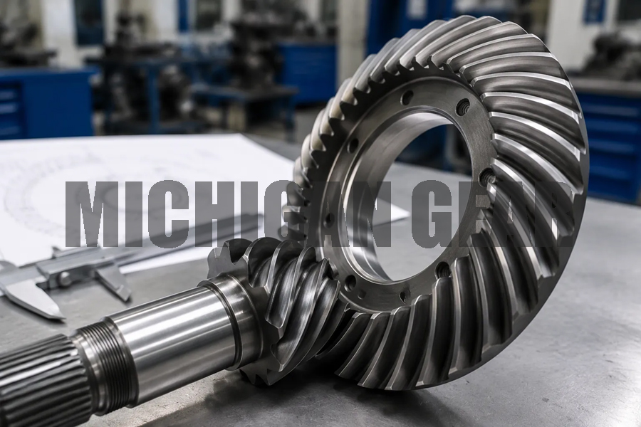
Spiral bevel gears are produced as a matched set. The ring gear and pinion are cut, heat-treated, and lapped or ground together to achieve the designed contact pattern and backlash. Replacing only one member introduces a mismatched pair with unpredictable contact characteristics .
The replacement set should arrive with both members marked with a matching serial number or pair identifier. If the supplier cannot confirm that the gears were produced and tested as a pair, the risk of unacceptable noise or premature failure increases significantly.
Documentation Package: What the Supplier Should Provide
The target supplier states that it provides six report types before shipping: drawing, dimension report, heat treatment report, accuracy report, material report, and flaw detection report. Each document serves a specific verification purpose.
| Document | What It Verifies | What the Buyer Should Check |
|---|---|---|
| Material report | Steel grade and chemical composition | Confirm the alloy matches the original specification (e.g., 20CrMnTi, 42CrMo, 9310) |
| Heat treatment report | Case depth and surface hardness | Confirm hardness within the specified range (typically 58–62 HRC for carburized gears) |
| Accuracy report | Tooth profile, lead, and spacing deviations | Confirm the grade meets the equipment requirement (DIN, AGMA, or ISO) |
| Dimension report | Mounting distance, bore, and keyway dimensions | Verify critical interface dimensions match the gearbox |
| Flaw detection report | Internal defects (cracks, inclusions) | Confirm no unacceptable indications |
| Contact pattern documentation | Tooth bearing under assembly | Request this explicitly—the target supplier’s listed reports do not mention contact pattern |
The contact pattern is the most important acceptance criterion for a spiral bevel gear set, and it is frequently omitted from standard documentation packages. The supplier should provide either photographs of the marking compound on the assembled teeth or, preferably, tape transfers lifted from the tooth surface . A dimensional report showing individual gear compliance does not substitute for contact pattern verification.
Installation Verification: What to Measure After Receipt
Backlash Measurement
Backlash is measured with a dial indicator on one gear while the other is held stationary. The indicator reading at the tooth flank shows the rotational free play . The specified backlash range depends on the application and gear size; the equipment manufacturer’s service manual provides the acceptance value.
Important limitation: correct backlash does not confirm correct assembly position. As noted above, multiple mounting positions can produce acceptable backlash while the contact pattern is incorrect.
Contact Pattern Check
Contact pattern verification requires coating the teeth of one member with gear marking compound, rotating the gears under light load, and inspecting the transferred pattern on the mating teeth. The pattern should be centered on the tooth flank, with the size and shape matching the supplier’s documentation or the equipment manufacturer’s specification .
For a replacement gear set, the supplier’s documented contact pattern—established during production testing—becomes the reference. The installer’s goal is to reproduce that pattern in the gearbox by achieving the correct mounting distance.
FAQ
Can I replace only the pinion gear and keep the original ring gear?
No. Spiral bevel gears are manufactured and tested as a matched pair. The lapping or grinding process creates a specific tooth contact relationship between the two members. Mixing a new pinion with a used ring gear produces unpredictable contact patterns and typically results in noise and accelerated wear.
The old gears have no visible mounting distance marking. What do I do?
Check the equipment manufacturer’s service manual first. If unavailable, the replacement gear supplier may have the original drawing or specifications for that gearbox model. If neither source is available, installation requires trial-and-error contact pattern development—a time-consuming process that should be performed by an experienced gear technician .
What is the difference between DIN and AGMA accuracy grades?
Both systems classify gear accuracy, but they use different scales and measurement conventions. DIN 3962 specifies grades 1–12, with lower numbers indicating higher precision. AGMA 2000 uses A0–A12, with higher numbers indicating higher precision . The supplier’s accuracy report should state the standard and grade used; if the original equipment specified a grade, the replacement should match or exceed it.
How can I verify the gear ratio without disassembling the gearbox?
Count the teeth on the replacement gears before installation and compare to the original ratio. If the original gears are already removed, the ratio is also documented in the equipment service manual or parts catalog. Do not rely on the ratio stamped or etched on the gear face—verify by counting .
What reports should I request before accepting shipment?
At minimum: material certification (steel grade), heat treatment report (hardness and case depth), dimensional inspection report, and accuracy report. Request contact pattern documentation—photographs or tape transfers—as an additional verification that the set was tested as an assembly. The target supplier’s six-report package covers most of these items, but contact pattern should be confirmed separately.
Is a flaw detection report necessary for replacement gears?
For critical applications—high-load, high-speed, or safety-related gearboxes—yes. Flaw detection (magnetic particle or dye penetrant) identifies surface and near-surface defects that dimensional inspection cannot detect. For lower-demand applications, material and heat treatment reports may be sufficient.
What is the most common mistake when installing replacement spiral bevel gears?
Setting backlash without verifying contact pattern. A gear set can achieve the specified backlash at the wrong mounting distance, producing a contact pattern that runs on the tooth edge or heel. This leads to noise, rapid wear, and potential tooth fracture under load . The correct procedure establishes the mounting distance first, then verifies backlash and pattern together.
Post time: Nov-09-2026