


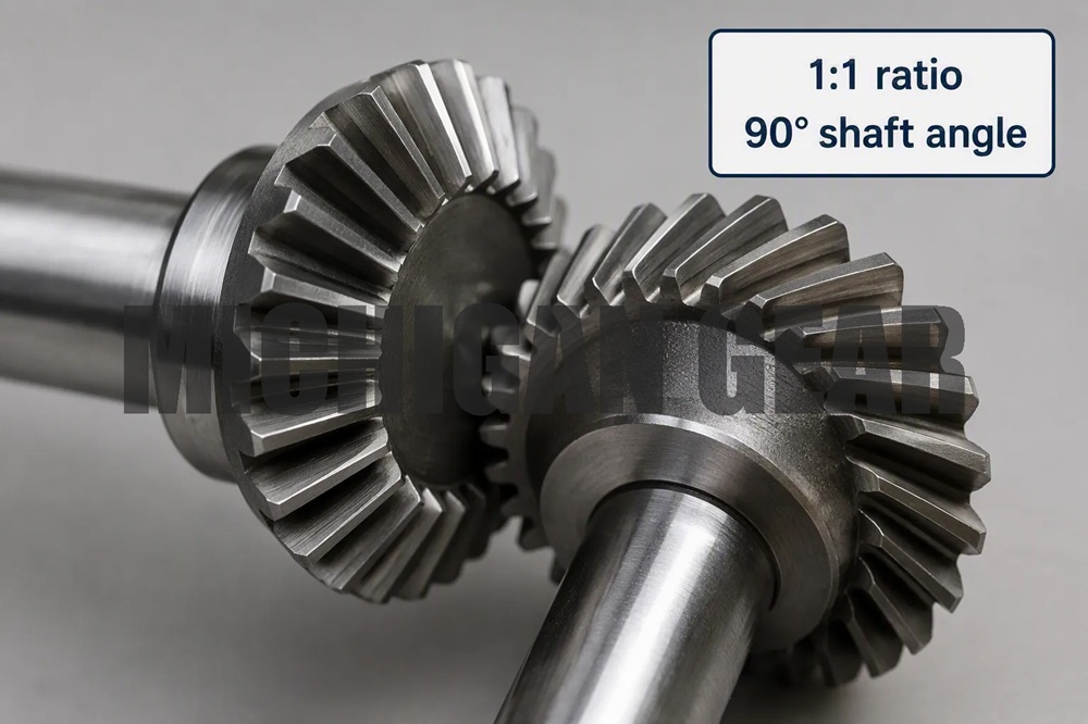
Quick Answer
Spiral bevel gears are preferred for high-speed and high-torque applications because their curved, oblique teeth engage gradually from one end of the tooth to the other, creating a rolling meshing action with minimal sliding friction. This design enables smooth, quiet operation at pitch line speeds of 5 to 40 m/s (with high-precision gears reaching 50 m/s), while distributing loads across multiple teeth to reduce impact stress and tooth breakage risk. Compared to straight bevel gears—which are limited to speeds below 5 m/s due to abrupt tooth contact—spiral bevel gears deliver superior load capacity, lower noise, and longer service life in demanding applications including helicopter transmissions, automotive differentials, and industrial gearboxes.
Key Takeaways:
●Gradual tooth engagement eliminates the abrupt impact loading that limits straight bevel gears to low-speed applications
●Rolling contact geometry achieves the highest mechanical efficiency among right-angle gearing types, with minimal sliding friction
●Load sharing across multiple teeth increases torque capacity and reduces surface fatigue compared to straight bevel designs
●Spiral angle (typically 35°) and pressure angle (typically 20°) are standardized parameters optimized for smooth power transmission
●ISO 23509-1:2025 provides the current international standard for bevel and hypoid gear geometry, covering spiral, straight, Zerol, and hypoid designs
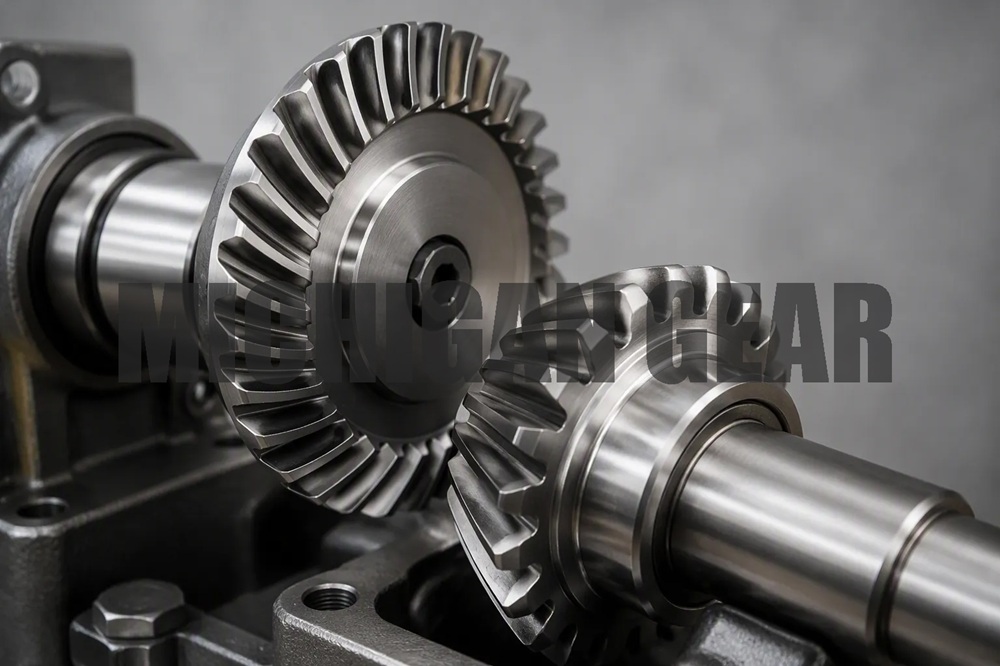
The Fundamental Problem: Why Straight Bevel Gears Fail at High Speeds
Straight bevel gears make contact abruptly along the full tooth flank, creating high impact stresses that increase exponentially with speed and load. This abrupt engagement limits straight bevel gears to pitch line speeds below 5 m/s and significantly below 1,000 RPM for small gears. At higher speeds, the repeated impact loading causes:
●Tooth breakage from fatigue crack initiation
●Excessive noise from the sharp contact transitions
●Vibration that accelerates bearing and shaft wear
●Surface fatigue (pitting) from concentrated contact stresses
For a procurement engineer specifying gears for an electric vehicle reducer operating at 15,000 RPM, or a helicopter main rotor transmission, straight bevel gears are simply not viable. The question becomes: what alternative provides the necessary speed capability without sacrificing torque capacity?
The Spiral Bevel Solution: Gradual Engagement Through Curved Geometry
Spiral bevel gears solve the high-speed problem through tooth geometry that changes the fundamental nature of contact.
How Curved Teeth Transform Meshing Action
Spiral bevel gear teeth are curved obliquely across the face of the gear, rather than cut straight. This curvature means contact begins at one end of the tooth (the toe) and progresses smoothly toward the other end (the heel) as the gears rotate. At any instant, two or more teeth are in contact, sharing the load and smoothing the transition between successive tooth engagements.
The practical consequence: Instead of a single abrupt impact, the load is applied progressively. This reduces peak contact stress, eliminates the primary noise and vibration source, and allows operating speeds that would destroy straight bevel gears.
Rolling Versus Sliding: The Efficiency Advantage
The meshing action of spiral bevel gears is predominantly rolling, with minimal sliding between tooth surfaces. This is fundamentally different from worm gearing, which relies on high sliding action that generates friction, heat, and wear.
| Gearing Type | Meshing Action | Relative Efficiency | Speed Capability |
|---|---|---|---|
| Spiral Bevel | Rolling (minimal sliding) | Highest | 5-40 m/s (50 m/s precision) |
| Hypoid | Rolling with some sliding | High | High |
| Worm | High sliding | Lowest | Moderate |
The rolling contact of spiral bevel gears means:
●Less heat generation at high speeds
●Slower backlash growth over service life (less wear)
●Higher efficiency (typically above 90-95%)
For a high-torque industrial gearbox running continuously, this efficiency advantage translates directly into lower operating costs and longer maintenance intervals.
Quantifying the Performance Advantage
Speed and Load Ratings
The performance difference between straight and spiral bevel gears is not marginal—it represents a fundamental capability gap:
| Parameter | Straight Bevel | Spiral Bevel |
|---|---|---|
| Maximum pitch line speed | < 5 m/s | 5-40 m/s (standard); up to 50 m/s (precision) |
| Typical pressure angle | 20° | 20° |
| Typical spiral angle | N/A (straight teeth) | 35° |
| Contact pattern | Abrupt, full-flank | Gradual, toe-to-heel progression |
| Load sharing | Single tooth at a time | Multiple teeth in contact |
| Noise characteristics | High (impact-dominated) | Low (rolling-dominated) |
| Primary failure mode | Tooth breakage at high speed | Surface fatigue (pitting) |
Real-World Validation: Helicopter Transmission Case Study
The OH-58D Kiowa helicopter main rotor transmission provides a documented example of spiral bevel gear performance in a high-speed, high-torque application.
Baseline configuration:
●Input speed: 6,016 RPM
●Maximum continuous power: 346 kW (464 hp)
●Reduction ratio (bevel stage): 3.26:1
●Pinion teeth: 19; Gear teeth: 62
●Module: 4.169 mm
●Mean spiral angle: 35°
●Face width: 36.83 mm
This transmission operates continuously at speeds far beyond the capability of straight bevel gears. The spiral bevel design was later modified for reduced noise (through transmission error optimization) and increased strength (through larger fillet radii), demonstrating the design’s adaptability to demanding performance requirements.
Material and Heat Treatment: Enabling the Geometry to Perform
The sophisticated geometry of spiral bevel gears demands materials and heat treatment that can withstand the resulting contact stresses and bending loads.
Typical Materials
Common spiral bevel gear materials include alloy steels such as 20CrMnTi, 20CrMo, and 40Cr. For aerospace applications, X-53 (AMS 6308) has been used as an alternative to conventional AISI 9310.
Heat Treatment
The standard heat treatment sequence for high-performance spiral bevel gears includes:
1.Carburizing: Creates a hard, wear-resistant surface layer
2.Quenching: Locks in the hardened case
3.Tempering: Provides core toughness to resist bending fatigue
This combination produces the hard surface (for contact fatigue resistance) and tough core (for bending strength) necessary for high-torque applications.
The Trade-Off: Torque Capacity Versus Efficiency
No gear type is universally superior. Spiral bevel gears occupy a specific performance envelope within right-angle gearing:
| Characteristic | Spiral Bevel | Hypoid | Worm |
|---|---|---|---|
| Meshing action | Rolling (pure) | Rolling + sliding | High sliding |
| Maximum single-stage ratio | 1:1 to 6:1 | 3:1 to 10:1 | 5:1 to 60:1 |
| Relative torque capacity | Lowest | High | Highest |
| Efficiency | Highest | High | Lowest |
| Speed capability | Highest | High | Moderate |
The critical insight for specifiers: Spiral bevel gears are the efficiency and speed choice for right-angle power transmission. If the application demands very high single-stage reduction ratios (above 6:1) or extreme torque capacity at low speed, worm gearing may be more appropriate—at the cost of efficiency.
For applications requiring high speed AND high torque, spiral bevel gears are typically used in multi-stage configurations: a spiral bevel first stage for right-angle change and speed reduction, followed by helical or planetary stages for further reduction. This approach leverages the speed capability of spiral bevel while achieving overall ratios beyond single-stage limits.
FAQ
Q1: What is the maximum speed a spiral bevel gear can handle?
Spiral bevel gears are recommended for pitch line speeds of 5 to 40 m/s in standard precision grades. High-precision, finish-ground gears can operate at speeds approaching 50 m/s. Straight bevel gears are limited to below 5 m/s due to abrupt tooth contact.
Q2: Why are spiral bevel gears quieter than straight bevel gears?
Spiral bevel gears achieve gradual tooth engagement from toe to heel, with multiple teeth sharing the load at any instant. This rolling action eliminates the abrupt impact loading that dominates straight bevel gear noise. NASA/Army research on helicopter transmissions demonstrated that further noise reduction is possible through transmission error optimization during gear grinding.
Q3: What is the standard spiral angle for spiral bevel gears?
The most common spiral angle is 35°, typically combined with a 20° pressure angle. The spiral angle determines the balance between axial thrust loading, contact ratio, and manufacturing complexity.
Q4: Are spiral bevel gears suitable for high-torque applications?
Yes, but with a critical distinction. Spiral bevel gears distribute loads across multiple teeth, reducing per-tooth stress compared to straight bevel designs. However, compared to worm gearing, spiral bevel gears have lower absolute torque capacity for a given size. For extremely high torque at low speed, worm gearing may be preferred. For high torque at high speed, spiral bevel gears are the appropriate choice, often in multi-stage configurations.
Q5: What materials are used for high-performance spiral bevel gears?
Common materials include 20CrMnTi, 20CrMo, and 40Cr alloy steels for industrial applications. Aerospace-grade spiral bevel gears may use X-53 (AMS 6308) or AISI 9310 (AMS 6265). The standard heat treatment is carburizing, quenching, and tempering to achieve high surface hardness with a tough core.
Q6: How does ISO 23509-1:2025 relate to spiral bevel gear design?
ISO 23509-1:2025 specifies the macro geometry of bevel gears, covering straight, skew, spiral, Zerol bevel, and hypoid designs. It provides the geometric framework for calculating factors used in bevel gear rating per ISO 10300. The standard is intended for experienced gear designers and replaced the 2016 edition in July 2025.
Q7: Can spiral bevel gears reverse direction?
Yes. Spiral bevel gears can transmit power in both directions, making them suitable for reversing drives in automotive and industrial applications. The thrust loading direction depends on the spiral angle and rotation direction, which must be considered in bearing selection.
Conclusion
Spiral bevel gears are chosen for high-speed and high-torque applications because their curved tooth geometry fundamentally changes the meshing action from abrupt impact to gradual rolling contact. This transformation enables:
●Speed capability 8-10 times higher than straight bevel gears
●Efficiency among the highest of all right-angle gearing types
●Load sharing across multiple teeth, reducing stress concentration
●Noise and vibration reduction critical for enclosed drive systems
The OH-58D helicopter transmission demonstrates spiral bevel gear performance in a real high-speed application: 346 kW at 6,016 RPM through a 3.26:1 reduction. For industrial applications ranging from electric vehicle reducers to heavy-duty gearboxes, spiral bevel gears provide the optimal combination of speed capability, efficiency, and reliability.
The trade-off is torque capacity relative to worm gearing and single-stage ratio limits of 1:1 to 6:1. For applications requiring both high speed and high overall reduction, multi-stage configurations (spiral bevel first stage plus helical or planetary stages) extend the capability envelope.
For procurement engineers, the actionable specification insight is this: define the pitch line speed first. If it exceeds 5 m/s, straight bevel gears are eliminated. Within the right-angle gearing options, choose spiral bevel for efficiency and speed, hypoid for offset axis layouts, and worm for high-ratio, low-speed torque transmission.
Post time: Oct-08-2026