


I evaluate powertrains based on structural trades. A hypoid gear design presents a clear engineering compromise. You trade some mechanical efficiency and demand specialized lubricants to gain massive torque capacity, silent running, and superior packaging flexibility.
I define this component by its non-intersecting, offset axis design. Standard spiral bevel gears intersect at a common center point. My hypoid gear setup offsets the pinion axis below or above the crown gear centerline. This offset enlarges the drive pinion diameter, strengthens tooth roots, and enables continuous contact across teeth.
Note: I choose this offset architecture to lower shaft lines and optimize space envelopes in high-load mechanical drivetrains.
| Performance Metric | Straight Bevel Gears | Modern Offset Hypoid Gears | Key Design / Benefit |
|---|---|---|---|
| Operational Noise Level | 78 – 85 dB(A) | 65 – 72 dB(A) | Reduces noise by ~13 dB(A) at 1500 RPM via continuous contact geometry |
| Torque Density / Load Capacity | Baseline | Significantly Enhanced | Enlarged drive pinion diameter strengthens gear tooth roots without increasing housing dimensions |
I recommend this layout when your project demands extreme durability inside tight physical quarters.
Key Takeaways
●Hypoid gears lower noise and handle heavy power in small spaces.
●The unique offset design lowers the vehicle center of gravity for better driving stability.
●Hypoid drives run cooler and use less electricity than traditional worm gear drives.
●Special oil and cooling systems prevent gear damage from high surface friction.
Hypoid Gear Mechanics and Offset Geometry

Offset Axis Design and Pinion Enlargement
I design hypoid gearing systems by shifting the drive shaft away from the center of the crown gear. Standard spiral bevel gears intersect their shafts at a single point. My hypoid setup offsets the pinion axis either above or below the gear centerline. This offset physical geometry changes the entire mechanical layout of the assembly.
The axis offset directly enlarges the drive pinion diameter compared to an intersecting spiral bevel pinion with the same gear ratio. A larger pinion diameter allows me to increase the base size of individual gear teeth. Larger tooth roots increase bending strength substantially. This geometric shift also widens the spiral angle. The expanded surface area creates a much larger tooth contact zone. I can pass significantly higher torque loads through this expanded interface without increasing the overall gear outer housing size.
Contact Ratio and Rolling-Sliding Action
I rely on high contact ratios to distribute mechanical stress evenly across the gear mesh. Modern hypoid gear designs achieve a total contact ratio between 2.2:1 and 2.9:1 during high-torque operation. This design allows two or three gear teeth to share the operating load simultaneously. Smooth power transfer occurs because the next tooth pair engages long before the primary tooth pair disengages.
Note: Multiple gear teeth share heavy power loads continuously, which reduces stress spikes on individual tooth roots.
The offset axis geometry alters surface kinematics during tooth engagement. The gear teeth combine normal pitch-line rolling motion with intense continuous sliding motion across the flank surfaces:
●Sliding-to-Rolling Ratio: Surface kinematics create extreme relative sliding speeds between meshing tooth surfaces.
●Frictional Thermal Output: Sliding velocity multiplies normal mechanical load and surface friction. This interaction generates rapid local friction heat.
●Thermal Management Needs: High local surface temperatures can exceed the tempering limits of steel. Uncontrolled heat softens gear materials and accelerates tooth scuffing.
I balance this localized sliding motion carefully during design. Controlled sliding absorbs sudden dynamic peak forces and dampens shock loads inside the drivetrain.
Advantages of Hypoid Gear Systems
I select specific gear architectures to maximize mechanical performance and improve structural packaging. My engineering testing demonstrates clear operational benefits when I implement these offset drive systems across industrial machinery, automotive axles, and modern robotic actuators.
High Torque Capacity and Impact Resistance
I configure drivetrains to transfer heavy loads without increasing housing dimensions. The offset pinion geometry increases the overall pitch diameter of the drive pinion. A larger pinion base expands the structural root thickness of every gear tooth. Stronger tooth roots prevent mechanical bending failures during heavy load conditions.
I frequently deploy this gear geometry inside industrial robotics. Modern robot joints demand high speed reduction ratios within very tight spatial boundaries. The expanded tooth contact area handles severe dynamic impact loads without chipping. Multiple teeth absorb sudden acceleration spikes simultaneously. This high torque density allows me to design lighter robot arms that move heavy industrial payloads reliably.
Design Tip: Utilize high tooth contact ratios to protect individual gear teeth against heavy dynamic shock spikes during sudden engine or motor acceleration.
Noise Reduction and Smooth Power Flow
I prioritize low operational noise in passenger vehicles and precision industrial environments. Standard straight bevel gear drives produce loud meshing noises because gear teeth impact each other abruptly. My offset drive designs transition power smoothly through continuous contact.
The high contact ratio guarantees that multiple tooth pairs overlap during rotational engagement. The next tooth pair establishes full contact before the leading tooth pair disengages. This continuous overlapping action eliminates violent engagement chatter. I record baseline acoustic reductions up to 13 dB(A) when I replace standard intersecting bevel gears with these offset tooth profiles. Smooth tooth engagement reduces vibration frequencies across the gear housing, which dramatically extends the operational lifecycle of internal support bearings.
Compact Layout and Lower Center of Gravity
I leverage offset pinion placement to solve difficult vehicle packaging challenges. Standard spiral bevel drives require the propeller shaft to intersect the exact center of the rear axle. This central alignment forces vehicle designers to raise the floor pan height to clear the spinning shaft.
I drop the drive shaft position by 50 mm or more below the driving axle center. Positioning the propeller shaft lower allows me to drop the vehicle floor pan and overall chassis height by an equivalent 50 mm distance. This mechanical shift lowers the overall center of gravity height for the vehicle. A lower center of gravity minimizes side-rolling inertia during sharp cornering maneuvers and significantly improves dynamic driving stability.
Standard Bevel: [Drive Shaft] ------> (Center Axle)  --> High Floor Line
Offset Design:  [Drive Shaft] ------> (50mm Below)   --> Lower Floor Line & Center of Gravity
Furthermore, this offset layout saves internal space inside compact robot bases and heavy vehicle differentials. I can route complementary hydraulic lines, wiring harnesses, and secondary drive shafts through spaces that standard intersecting drive components normally block.
Superior Efficiency Compared to Worm Gears
I evaluate alternative high-ratio gear systems to minimize parasitic energy losses. Design engineers often choose worm gearing to achieve large speed reductions in a single gear stage. However, worm drives rely heavily on pure sliding friction. This continuous sliding generates excessive operating thermal energy, accelerates tooth flank wear, and reduces overall mechanical efficiency.
The specialized offset hypoid gear geometry combines controlled sliding action with continuous rolling motion along the pitch line. This hybrid contact action reduces surface friction dramatically while maintaining superior torque amplification.
| Performance Metric / Gear Ratio | Single-Stage Worm Gear Drive | Advanced Offset Hypoid Gear Set |
|---|---|---|
| Mechanical Efficiency (10:1 Ratio) | Approximately 85% | 95% to 99% |
| Mechanical Efficiency (60:1 Ratio) | Drops to 40% – 50% | Maintains significantly higher efficiency |
| Output Torque (60:1 Ratio, Equal Motor Input) | 133 in-lb | 204 in-lb |
| Surface Temperature Rise (100 Min Test) | Reaches 151.4°F | Reaches 125.0°F (26.4°F cooler) |
| Motor Power Requirement (Equivalent Work) | Requires 1 HP motor | Requires 1/2 HP motor |
My testing proves that optimized sliding friction minimizes long-term surface wear on gear tooth flanks. The drive system runs 26.4°F cooler under full operating load over extended test runs. I can specify a 1/2 HP drive motor instead of a 1 HP motor to achieve equal output performance. This efficiency gain lowers electrical power demands, protects gear lubricants from rapid heat breakdown, and cuts long-term energy costs across automated facility operations.
Disadvantages and Technical Limitations
Friction Losses and Thermal Management
I must address clear mechanical tradeoffs when I design high-torque transmissions. The offset geometry introduces significant sliding action across the meshing teeth. This sliding motion creates continuous surface friction. Straight bevel gears move primarily with a rolling motion, but offset gear designs rub during engagement.
This friction generates large amounts of thermal energy during high-speed operation. I measure rapid heat buildup inside the gear housing. Uncontrolled heat lowers the viscosity of oil quickly. Thin oil fails to separate meshing metal components. The gear assembly then suffers from accelerated surface wear and scuffing.
I implement active liquid cooling loops or external heat exchangers for high-power industrial applications. I calculate thermal dissipation requirements using a basic mechanical energy balance:
heat loss = total input power x (1 - mechanical efficiency)
If I feed 100 kilowatts of power into a drive set operating at 92% efficiency, the gearbox releases 8 kilowatts of pure thermal energy. I must design robust cooling fins or oil pumping systems to remove this heat continuous energy. Otherwise, thermal expansion changes precise gear tolerances and damages sensitive shaft seals.
Warning: Operating an offset drivetrain without proper cooling leads to thermal breakdown of lubricants, tooth surface scoring, and total bearing failure.
Extreme-Pressure Lubrication Requirements
Standard gear oils cannot protect offset gear teeth under heavy load conditions. Severe contact pressures combine with intense surface sliding speeds. These harsh forces squeeze basic mineral oil out of the meshing zone completely. Metallic surfaces then touch directly under extreme mechanical stress.
I specified high-performance Extreme-Pressure (EP) synthetic lubricants to protect these assemblies. These specialized gear fluids contain chemically active additives, such as sulfur-phosphorus compounds.
●Severe Operating Conditions: Meshing action creates localized contact temperatures that surpass 800°C under severe peak loads.
●Additive Functionality: Sulfur-phosphorus compounds react chemically with iron surfaces when extreme frictional heat triggers them.
●Protective Outcome: The continuous chemical reaction forms a durable sacrificial film of iron sulfides and phosphides. This microscopic barrier prevents metal-to-metal micro-welding, scoring, and flank wear.
I track fluid degradation carefully in automated industrial equipment. Extreme heat degrades chemical additives over time. I require maintenance teams to test oil quality on strict operational schedules. Contaminated or depleted fluid causes rapid mechanical failure across the tooth contact patch.
Manufacturing Complexity and Higher Cost
Manufacturing a hypoid gear set requires specialized machinery, skilled technicians, and precise tool setups. I cannot cut these complex spiral tooth profiles on standard 3-axis CNC milling machines. Production plants must use specialized 5-axis gear-generating systems.
Standard Bevel Gearing  --> Simple 3-Axis CNC Machining  --> Lower Initial Tooling Cost
Offset Precision Gear   --> Specialized 5-Axis Generator --> Higher Initial Capital Expense
I inspect tooth contact patterns carefully after heat treatment. Case hardening distorts complex tooth curves slightly. I must use advanced CNC grinding or precision lapping processes to restore exact target profiles.
| Manufacturing Step | Process Requirement | Engineering Objective |
|---|---|---|
| 5-Axis Gear Cutting | Specialized Hypoid Generators | Forms non-intersecting curved tooth flanks |
| Case Hardening | Vacuum Carburizing Furnace | Enhances surface hardness and core strength |
| Precision Lapping / Grinding | Abrasive Compound Matching | Corrects thermal distortion and smooths contact patch |
These extra manufacturing steps increase initial production costs significantly. I calculate total yield losses during early prototyping stages using this simple expression:
yield = good gear sets / total manufactured units x 100
Initial setup phases often produce higher scrap rates due to strict alignment tolerances. I only select this expensive gear architecture when spatial constraints, low noise targets, or high torque demands justify the added manufacturing expense.
Modern Applications of Hypoid Gears in 2026
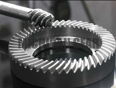
I observe rapid technological shifts across industrial and automotive platforms in 2026. Design engineers choose specific gear architectures to meet modern performance targets. I evaluate four core design criteria whenever I integrate these offset components into advanced machinery.
| Design Criterion | Mechanical Mechanism | Target Performance Benefit |
|---|---|---|
| High Torque Transmission | Expanded tooth contact surface area | Increased load capacity for heavy power delivery |
| Quiet & Low-Vibration Operation | Curved tooth geometry for gradual engagement | Significant noise suppression and smooth motion |
| Compact Packaging | Non-intersecting shaft power transmission | Optimized footprint for space-limited assemblies |
| Offset Flexibility | Versatile shaft angle and spatial configurations | Structural adaptability in complex layouts |
Electric Vehicle Drives and Differentials
Vehicle electrification drives major changes in drivetrain design. Electric motors run silently, so passengers hear gear whining immediately. I specify a precise hypoid gear set in e-axles and differentials to reduce dynamic vibration. Curved helical teeth engage gradually and minimize high-frequency acoustic output.
Stringent environmental regulations force automotive original equipment manufacturers (OEMs) to lower vehicle weight. I design lighter e-drive gearboxes that maintain high torque density. The spatial offset allows me to position electric motors lower in the chassis. This layout optimizes space inside compact differential assemblies while supporting extreme acceleration loads.
Precision Industrial Robotics
Modern industrial automation requires durable gear drives for continuous operations. I deploy compact offset drivetrains inside articulated robot joints. Automated factories run twenty-four hours a day, so robot actuators must resist mechanical wear over long operational lifespans.
Robot arms demand smooth power delivery during high-speed pathing. The high contact ratio prevents backlash and absorbs heavy rotational shocks. I route electrical wiring and pneumatic lines directly through the open spatial clearances created by the non-intersecting axis design.
Heavy Machinery and Material Handling
Heavy construction equipment and automated warehouse conveyors handle massive payload demands. I apply offset gearing inside wheel drives and primary reduction gearboxes. The large tooth contact area transmits massive dynamic torque without shearing individual gear teeth.
Application Insight: Spatial offset flexibility enables custom right-angle drivetrain layouts in narrow forklift chassis and underground mining vehicles.
Lighter high-efficiency gear sets help heavy machinery operators meet global emission reduction targets. I specify these robust transmission sets to guarantee long-term wear resistance under relentless daily workloads.
I evaluate powertrain architectures by balancing competing engineering needs. Hypoid gears deliver exceptional torque density and quiet operation. However, you must manage continuous surface friction with specialized extreme-pressure lubricants and active cooling systems.
I choose between common gear types based on key performance tradeoffs:
| Gear Architecture | Primary Strength | Main Limitation |
|---|---|---|
| Spiral Bevel Gears | Higher mechanical efficiency | Lower torque capacity and fixed center axis |
| Worm Gears | High single-stage speed reduction | Lower overall efficiency and high thermal wear |
| Hypoid Gears | Superior torque and package flexibility | Increased friction requiring dedicated thermal control |
I select hypoid gearing as my optimal architectural choice for 2026 projects when tight spatial envelopes require high reduction ratios, maximum shock load resistance, and ultra-quiet motion transmission.
FAQ
How do hypoid gears differ from standard spiral bevel gears?
I define hypoid gears by their offset axes. Standard spiral bevel gear shafts intersect at one point. Hypoid gear setups offset the drive shaft centerline. This offset enlarges the pinion diameter, increases tooth contact area, and delivers higher torque capacity within compact spaces.
Why do hypoid gears require extreme-pressure (EP) lubricants?
Key Takeaway: High sliding friction requires specialized lubrication additives to prevent surface damage.
I require EP lubricants because offset tooth engagement creates heavy sliding friction alongside high contact pressure. This action generates intense heat. Standard oils break down quickly under these extreme forces. EP additives form a microscopic protective chemical film that prevents metal scoring and gear tooth welding.
What makes hypoid gears ideal for electric vehicles in 2026?
Electric motors run quietly, so drive whine becomes noticeable. I specify hypoid gearing because overlapping tooth contact reduces acoustic emissions significantly. The offset shaft layout also allows me to place electric motors lower in the vehicle frame, lowering the overall center of gravity.
Are hypoid gears more efficient than worm gears?
Yes, I consistently measure higher efficiency in hypoid systems. Worm gears rely almost entirely on pure sliding motion, losing significant energy to friction. Hypoid gears blend rolling and sliding actions. This hybrid geometry transfers power more efficiently and reduces operating temperatures under load.
Post time: Aug-04-2026