


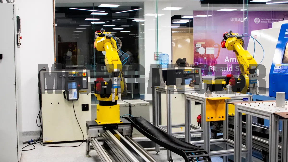
I define a miter gear as a specialized bevel gear with a 1:1 gear ratio. I use these precise mechanical components to change rotational direction by 90 degrees inside compact housing units. They transfer motion directly between perpendicular shafts without altering mechanical speed or torque output. In my engineering work, I regularly integrate Miter Gear drives into articulated wrist joints, mobile rover steering systems, and compact exoskeleton actuators. These versatile mechanisms deliver optimal performance across moderate-speed and moderate-load robotic systems. They maximize 90-degree spatial efficiency in tight setups where clean, reliable right-angle power transmission remains paramount for overall system design.
Key Takeaways
●Miter gears change rotational power direction by ninety degrees without changing speed or torque output.
●Perpendicular motor mounting saves valuable space inside compact robotic joints and manipulator wrists.
●Mobile rovers and wearable exoskeletons use angular drives to improve spatial efficiency and balance.
●Operating miter gears under moderate loads prevents excessive heat buildup and extends gear life.
Miter Gear Integration in Compact Robotic Joints
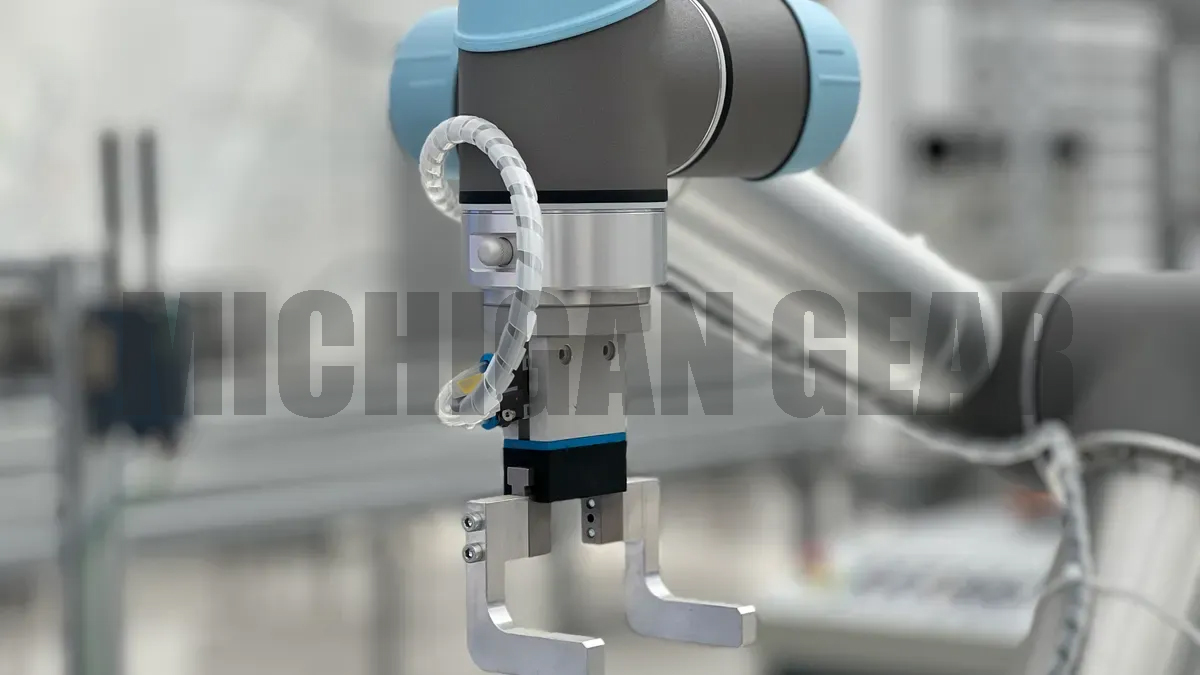
I design robotic joints to fit inside strict mechanical envelopes. Standard inline drive systems present major space challenges in modern automation. Long motor assemblies extend past desired joint footprints when I align motor shafts directly with driven axes. Integrating right-angle power transfer solves this spatial constraint effectively. I rely on precise angular component placement to optimize internal frame volume. I systematically analyze space constraints before choosing drive configurations. Efficient spatial planning allows me to construct tight, streamlined joint enclosures.
Space-Saving Right-Angle Drives
I mount electric motors perpendicular to the driven joint axis in compact robotic frames. This right-angle configuration relocates the main motor body along the internal structural housing. I redirect rotational force precisely 90 degrees using a Miter Gear assembly. This layout reduces the overall projection length of the drive assembly substantially.
I utilize this compact mounting scheme across several robotic joint configurations:
●Arm pitch and roll joints where protruding motor bodies would limit range of motion
●Mobile base steerable pod units where horizontal height constraints exist
●Compact robotic wrists requiring minimal outer diameter profiles
Placing drive motors parallel or transverse to structural limbs allows me to keep joint housings slim. I eliminate awkward outer bulges in the robot frame. Smaller housings reduce total structural weight. Lower weight improves overall dynamic responsiveness during rapid acceleration phases. Internal wire routing also becomes much cleaner and safer. I run electrical cables through open channels beside the perpendicular motor casing without risking cable pinching or abrasion during full joint rotations.
Preserving 1:1 Speed and Torque Transmission
I select specialized bevel drives with equal tooth counts when I need direct power routing without changing speed profiles. The driven shaft receives identical rotational velocity and output torque from the input shaft. I handle primary speed reduction elsewhere in the drive train using dedicated planetary gearheads. This design split isolates pure angular redirection from high-ratio torque multiplying tasks. I maintain precise sync between input and output shafts. Direct power transfer ensures predictable position feedback across automated motion cycles.
I maintain continuous operational performance by operating these gear sets strictly within moderate speed and moderate torque limits. High dynamic loads produce excessive friction between meshing gear teeth. I monitor thermal parameters carefully because uncontrolled heat causes metal expansion inside closed joint casings. Thermal expansion degrades the precision tolerance of tooth engagement. Expanded components increase mechanical resistance, accelerate surface wear, and lower total transmission efficiency below target thresholds.
I maintain high 90-degree mesh efficiency and prevent mechanical binding by matching load limits directly to housing heat dissipation rates.
I regularly measure thermal stability during continuous joint cycling tests. I keep operational speeds within moderate ranges to ensure uniform contact stress along gear tooth profiles. This conservative thermal management preserves exact angular alignment across thousands of motion cycles. Proper speed management eliminates unwanted backlash shifts caused by thermal swelling in aluminum or steel housings.
Furthermore, maintaining moderate operating parameters protects delicate synthetic lubricants from thermal breakdown. Clean lubricant films protect meshing surfaces from micro-pitting under repetitive cycling. I maintain steady operational control across long duty cycles by protecting every mechanical interface from excessive heat build-up. My designs achieve smooth, predictable control while maximizing mechanical longevity in space-constrained joint applications.
Angular Drives in Robotic Manipulators
I design robotic manipulators to execute complex automation tasks inside tight industrial spaces. Articulated arm links require efficient mechanical power routing across multiple rotatable joint axes. Motor placement creates severe mechanical layout bottlenecks when I route mechanical power straight down the arm segments. Angular drive systems solve this spatial issue by turning rotational force precisely across intersecting shaft axes. I position internal angular drives inside manipulator arms to create slim structural profiles. This mechanical approach keeps the moving payload close to the arm structure, which stabilizes system balance during rapid motion sequences. I design these joint housings to distribute structural forces evenly across the robot framework.
Miter Gear Mechanisms in Manipulator Wrists
Robotic wrist joints demand extreme spatial efficiency. I install specialized right-angle gear sets to route rotational power smoothly through pitch, yaw, and roll joint axes. These mechanical components allow me to align internal drive shafts along the main arm link while transferring rotational movement across the perpendicular wrist joint axis. I route central control wiring directly through open internal channels without pinching electrical cables during rapid wrist motion cycles.
I evaluate key mechanical performance parameters when I integrate these angular drives into multi-axis robotic wrists:
| Attribute | Value |
|---|---|
| Configuration | Coaxial shaft driving a series of miter gears for wrist yaw joint |
| Reduction Ratio | 3.33:1 |
| Max Joint Torque | 1.256 Nm |
This specific layout transmits smooth rotational power through intersecting shaft angles. A single Miter Gear unit changes the physical direction of the drive torque without altering the underlying rotational speed. Secondary gear stages provide the necessary mechanical speed reduction. This separation of mechanical duties isolates spatial angle changes from high-ratio torque conversions. The assembly keeps the wrist housing light while protecting internal drive components from excessive side-load wear during continuous operation.
Compact Motion Control for Robotic Grippers
Robotic end effectors require lightweight drive mechanisms to maintain high dynamic responsiveness during operation. I place electric drive motors parallel to gripper palm frames to keep finger drive mechanisms compact. This mechanical orientation prevents long motor bodies from sticking out behind the main gripper mounting plate. Right-angle bevel pairs route motor rotation ninety degrees directly into the lead screws or rack-and-pinion rails that actuate the gripping fingers.
I utilize this perpendicular mounting approach to build symmetrical, twin-finger gripping mechanisms. The main input shaft turns two opposing bevel pairs simultaneously. This uniform power transfer drives both gripper jaws inward at identical speeds. The direct dynamic transmission preserves rotational balance and provides smooth, linear jaw movement across the full mechanical stroke range. I maintain precise finger position tracking because equal tooth counts prevent mechanical slip between parallel driven shafts. Synchronized jaw motion ensures predictable handling when grasping fragile workpieces.
This layout also improves tactile force feedback during delicate object contact. The direct dynamic connection lets motor current sensors detect exact gripping resistance without dynamic control lag. I operate these robotic gripper assemblies strictly within moderate torque and moderate speed thresholds. Conservative operating parameters prevent harmful thermal expansion inside the small palm enclosure. Preventing excessive heat build-up keeps internal mechanical tolerances tight. This approach guarantees consistent clamping forces and protects precision components across thousands of pick-and-place cycles. I inspect these mechanical connections regularly to ensure long-term motion repeatability.
Mobile Robotics and Steering Systems
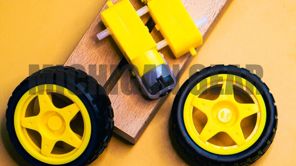
I engineer mobile platforms to navigate complex environments with high precision. Standard drive layouts consume valuable internal volume inside automated vehicle frames. Relocating drive components creates clean structural space for batteries, sensors, and central control electronics. I integrate specialized angular drives to maintain high mobility while saving internal frame space.
Steering Modules for AGVs and AMRs
I design steerable drive modules for Automated Guided Vehicles (AGVs) and Autonomous Mobile Robots (AMRs). These autonomous units require independent 90-degree power routing inside tight wheel pods to achieve full omnidirectional movement. I mount electric drive motors vertically inside the pod housing. This perpendicular orientation frees up horizontal floor area above the wheel mechanism.
I install a Miter Gear pair inside each steering module to transfer motor rotation directly to the horizontal wheel axle.
●Vertical motor mounting reduces horizontal footprint inside the vehicle chassis.
●Right-angle power redirection turns drive torque precisely 90 degrees.
●Equal tooth counts transfer full motor speed and torque without dynamic loss.
This compact arrangement keeps the steering axis aligned with the wheel center. The streamlined assembly protects drive components from ambient dust and operating debris.
Differential Drives in Exploration Rovers
Exploration rovers traverse unpredictable terrain where ground contact changes constantly. I design differential drive assemblies that distribute mechanical power across flexible rocker-bogie suspension limbs. Angular power transmission turns rotational force from central drive shafts into the moving suspension joints. This structural layout keeps heavy drive motors mounted close to the main body center, which stabilizes vehicle balance over steep inclines.
Managing backlash and impact loads remains vital in unpaved operational settings. I set tight mesh tolerances during mechanical assembly to minimize angular play during directional changes. Uncontrolled backlash causes positioning errors in autonomous navigation systems. I manage sudden impact forces by keeping operational parameters within moderate torque and speed thresholds. Operating within safe mechanical limits prevents tooth surface fatigue, reduces thermal expansion inside sealed drive housings, and ensures continuous motion accuracy across long rover missions.
Actuation in Humanoids and Exoskeletons
Hip and Ankle Joints in Humanoid Frames
I design humanoid robot legs to replicate natural human movement inside tight structural frames. Space limitations around hip and ankle joints force me to place electric motors away from joint pivot lines. Direct inline motor placement creates wide, awkward legs that hinder natural walking strides. I mount drive motors vertically inside structural leg channels to eliminate unnecessary width.
Right-angle transmission components route rotational power across intersecting joint axes. I install a Miter Gear assembly inside the compact joint housing to turn motor rotation ninety degrees without altering input torque or speed output. Isolating pure directional changes from secondary speed reduction stages maintains precise leg position control across automated walking cycles. I operate these humanoid joint drives strictly within moderate speed and load limits. Keeping operational loads within conservative bounds prevents thermal expansion from degrading tooth alignment inside closed aluminum joint frames.
Wearable Drives for Lower-Limb Exoskeletons
Wearable lower-limb exoskeletons demand slim structural profiles to ensure user comfort and physical safety. Protruding drive assemblies disrupt human balance and catch on environmental obstacles. I position flat electric actuators parallel to the user’s outer thigh and calf support bars. This mechanical layout keeps heavy structural components close to the wearer’s body center.
Right-angle bevel pairs turn rotational force ninety degrees directly into the knee and ankle pivot shafts. This perpendicular mounting scheme creates a compact drive envelope around human joint structures. I utilize specific operational parameters to maintain steady performance during wearable assistance tasks:
●Perpendicular power redirection minimizes lateral device width along the limb.
●Equal input and output speeds ensure predictable movement timing.
●Moderate load thresholds preserve tooth contact surfaces during repetitive stride cycles.
I measure mechanical housing temperatures regularly during continuous human walking trials. Operating below heavy thermal limits protects internal synthetic lubricants from sudden breakdown. Clean lubrication layers minimize surface friction, eliminate mechanical binding, and prolong drive longevity across daily operation.
I integrate Miter Gear assemblies to achieve reliable 90-degree power transmission inside space-constrained robotic frames. These reliable mechanisms maintain a strict 1:1 gear ratio. They redirect rotational motion smoothly without altering output speed or mechanical torque. My engineering projects deploy these drives inside articulated manipulators, mobile platform steering modules, and wearable human-assistive robotics.
Operating these precision drives within moderate load and speed bounds remains essential to maximize gear mesh longevity.
I prevent thermal expansion and protect internal lubricant layers by respecting these operational boundaries. This disciplined design strategy guarantees continuous dynamic accuracy across advanced modern robotic systems.
FAQ
What is the main purpose of a miter gear in robotics?
I use miter gears to change the direction of rotational power by 90 degrees inside tight robotic frames. They feature equal tooth counts on both bevel components. This unique design transfers motion directly between perpendicular shafts without altering your system’s rotational speed or mechanical torque.
Why do I choose miter gears over standard spur gears in robotic joints?
I select miter gears when my mechanical designs face severe spatial bounds. Standard spur gears route power along parallel shafts, which lengthens joint housings. Miter gears allow me to mount drive motors perpendicularly, saving crucial internal volume inside compact arms, wrists, and legs.
Do miter gears change the speed or torque of my robotic drive?
No, miter gears maintain a strict 1:1 gear ratio. They redirect motion across intersecting axes while preserving identical input speed and output torque. I handle any necessary speed reduction or torque multiplication using separate gearboxes elsewhere in the drive train.
How do I prevent excessive wear on miter gears during continuous operation?
I keep operational loads and operating speeds within moderate thresholds. High speeds produce internal heat, causing thermal expansion that disrupts precise tooth mesh alignment. Operating within safe limits preserves synthetic lubricant layers, prevents tooth surface fatigue, and extends mechanical service life.
Post time: Aug-20-2026