


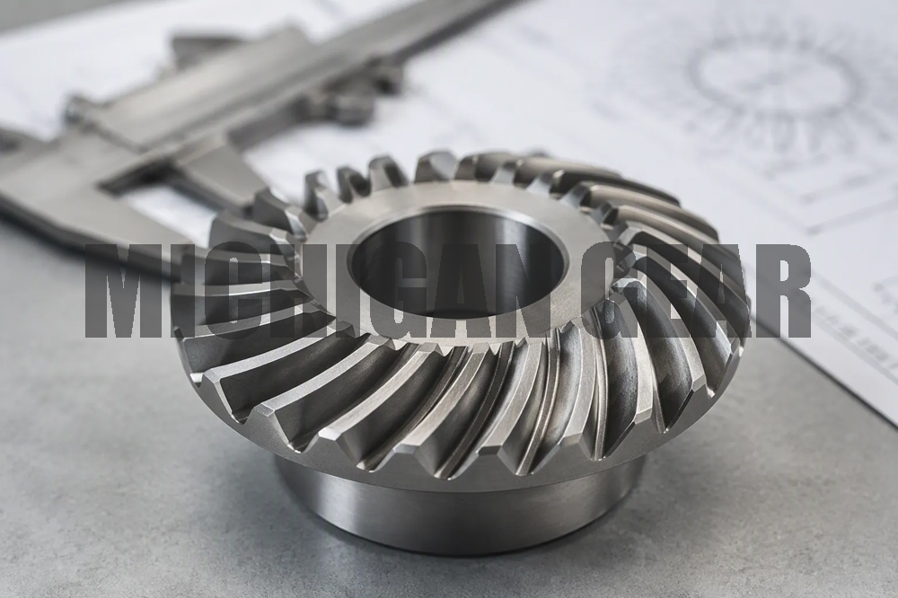
Knowing which specs to check saves time and prevents costly mistakes. I always verify eight critical details before buying a Miter Gear: gear ratio, pressure angle, pitch, number of teeth, material, bore size, mounting style, and quality grade. This article walks through each specification in order, helping you make an informed decision.
Key Takeaways
- Always match gear ratio, pressure angle, pitch, and tooth count between mating gears to prevent noise and failure.
- Choose the 20° pressure angle for high-load applications; it offers stronger teeth than the 14.5° angle.
- Verify material, quality grade, bore size, and mounting style to ensure durability and proper installation.
Miter Gear Geometry and Tooth Specifications
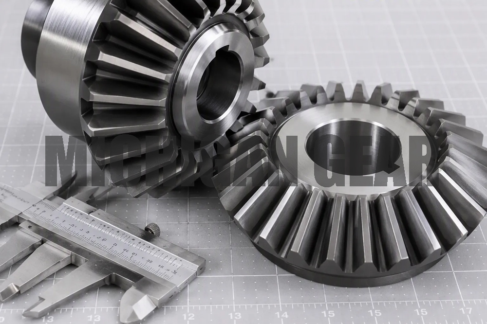
Before I select any gear, I always start with the tooth geometry. Four specifications define how a Miter Gear meshes with its partner: pressure angle, pitch, number of teeth, and gear ratio. These four values must match exactly between the two mating gears. If even one differs, the teeth will not engage properly, causing noise, vibration, and premature failure.
Pressure Angle and Pitch
The pressure angle describes the angle at which the tooth face transmits force between meshing gears. I commonly see two standard values: 14.5° and 20°. The 14.5° angle was the historical default, but the 20° angle has become the modern standard for most industrial applications.
A higher pressure angle results in a wider tooth base, which significantly increases the gear’s bending strength and load-carrying capacity.
This difference matters more than many buyers realize. Let me compare the two options directly:
| Property | 14.5° pressure angle | 20° pressure angle |
|---|---|---|
| Tooth root thickness | Narrower | Wider |
| Load capacity | Lower | Higher |
| Contact ratio | Higher (smoother) | Lower (slightly noisier) |
| Minimum pinion teeth (avoid undercut) | ~32 | ~17–18 |
For high-load applications, I recommend the 20° pressure angle. The wider tooth base resists bending forces far better. The trade-off is a slightly lower contact ratio, which means marginally more noise. The 14.5° angle still works well for light-duty, precision applications where smoothness matters more than raw strength.
Pitch defines the tooth size. In inch-based systems, I use diametral pitch (DP), which equals the number of teeth divided by the pitch diameter. Metric systems use module, the inverse concept. Two mating gears must share the same pitch value. A DP 16 gear will not mesh with a DP 20 gear, regardless of how well other specs align.
Number of Teeth and Gear Ratio
A true Miter Gear set always has a 1:1 gear ratio. This means both gears in the pair have the same number of teeth. The shafts intersect at exactly 90°. This configuration changes the direction of rotation without changing speed or torque.
| Aspect | Evidence |
|---|---|
| Definition | A miter bevel gear set is defined by equal tooth count (1:1 ratio) and right-angle (90°) shaft intersection. |
| Performance implication of deviation | A 1:1 ratio means no speed change; using a miter set for speed reduction is not recommended, as it cannot slow down or speed up the output shaft. |
| Design guidance | For applications requiring a non-1:1 ratio, an alternative bevel gear design should be selected instead of a miter set. |
I often see buyers mistakenly order a miter set hoping to achieve speed reduction. That approach fails. If you need a ratio other than 1:1, you need a different bevel gear configuration entirely.
The number of teeth directly affects smoothness and load distribution. More teeth generally mean smoother operation with less vibration. Fewer teeth allow higher torque capacity per tooth but increase noise. The tooth geometry, governed by AGMA quality numbers, directly affects meshing accuracy and load distribution. Runout and spacing errors cause vibration and uneven wear. When tooth geometry is incorrect, I see failure modes like top-fat and root-thin profiles, which disrupt proper meshing contact, or unilateral errors where one flank is correct and the other is oversized. These problems trace back to incorrect pressure angle settings or tool misalignment during manufacturing.
I always verify the tooth count on both gears matches exactly. I also confirm the pressure angle and pitch values appear on the manufacturer’s spec sheet. These four geometry specs form the foundation. Getting them right prevents the majority of field failures I encounter.
Miter Gear Material and Quality Grade
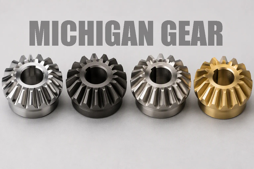
Once I confirm the tooth geometry, I shift my attention to what the gear is made of and how precisely it is manufactured. These two factors determine whether the gear survives its working environment and how quietly it runs. Material choice affects strength, wear resistance, and noise. Quality grade controls backlash and load capacity. Both deserve careful review before I place an order.
Material Selection
Steel remains the most common choice for industrial miter gear applications. Carbon steel offers easy machining and good wear resistance at a low cost. Alloy steel, such as AISI 4140, provides greater strength and can be carburized for surface hardness up to HRc 63. Stainless steel contains at least 11% chromium. Grade 303 adds sulfur for improved machinability. Grade 316 includes molybdenum for superior corrosion resistance. The added strength of stainless steel allows same-size gears to handle more load and resist wear for more cycles.
| Material | Key Strength/Wear Characteristics | Typical Applications |
|---|---|---|
| Carbon Steel | Easy to machine, good wear resistance, can be hardened, inexpensive | General industrial gearing |
| Alloy Steel (AISI 4140) | Stronger than carbon steel, can be carburized/case hardened | High-load bevel gears, worms |
| Stainless Steel (303, 316) | ≥11% chromium; 303 machines well; 316 resists corrosion | Food, marine, medical equipment |
| Brass | Moderate strength, low friction, corrosion resistant | Light-duty instruments |
| Plastic (Acetal) | Low modulus, dampens vibration, quieter operation | Home healthcare, light machinery |
Plastic gears deserve special attention. In a home healthcare bed motor drive, acetal gears reduced operating noise significantly compared to original powder metal gears. The lower modulus of plastic teeth allows them to deform and absorb impacts from misalignment and tooth errors. This dampening effect makes plastic gears quieter than metal gears of higher AGMA quality classes. Plastic teeth also distribute load across more teeth through deflection, enhancing load-bearing capacity through load-sharing. However, plastic suits lighter-duty applications only. Metal gears provide exceptional strength for heavy loads and high torque.
Quality Grade and Load Capacity
Quality grade describes manufacturing accuracy. AGMA class numbers indicate tooth spacing, profile, and runout tolerances. Higher grades mean tighter tolerances, less backlash, and smoother meshing. Lower grades cost less but produce more noise and vibration. I match the grade to the application’s speed and precision demands.
Load capacity ratings follow established standards. ISO 10300 covers bevel gear strength rating internationally. AGMA 2003-C10 provides the American standard for root bending stress and pitting calculations. The Gleason Q-factor method rates bending stress using diametral pitch, face width, and geometry factors. Loaded Tooth Contact Analysis uses finite element methods for high accuracy under real conditions. Since a Miter Gear is simply a bevel gear with a 1:1 ratio and 90° shaft angle, these methods apply directly.
Manufacturers test gear sets under simulated operating conditions. They check noise, vibration, and heat generation. For example, a spiral bevel gear set for a power tool undergoes testing at 3,000 RPM to confirm smooth operation and load capacity. Certifications from ANSI and CEN validate that gear sets meet stringent performance requirements.
I always request the quality grade and load rating data before purchasing. These numbers tell me whether the gear will perform reliably in my specific application.
Mounting and Installation Specifications
After confirming material and quality grade, I turn my attention to how the gear physically attaches to your machine. Bore size and mounting style determine whether installation goes smoothly. Backlash and alignment determine whether the gear set runs quietly and lasts.
Bore Size and Mounting Style
The bore must match your shaft diameter precisely. For metal gears, I look for an H7 tolerance, which means zero plus tolerance. Plastic gears typically use H8. Both ensure a minimum nominal size with slight oversizing to fit precision shafts. A bore that is too loose creates eccentricity. A bore that is too tight makes installation difficult.
Mounting style affects how easily you can secure the gear. Set screw mounting offers simplicity but concentrates force at one point. Keyed mounting provides positive torque transmission and prevents slippage. Clamp hub mounting distributes force evenly around the shaft and allows fine positional adjustment. I choose based on the torque level and how often I need to remove the gear.
Backlash and Alignment
Backlash refers to the clearance between non-driving flanks of meshing teeth. Quality grade influences this value, but mounting accuracy matters just as much. Mounting distance errors change backlash. The change equals actual measured backlash at the heel minus theoretical backlash. For a standard Miter Gear with 45° pitch angles, displacement along the pinion axis causes the most significant backlash change.
Contact pattern analysis reveals alignment problems. I apply marking compound and rotate the pair to observe the pattern.
| Observed Contact Pattern Symptom | Related Misalignment/Installation Cause |
|---|---|
| Pattern too close to heel | Gear position, mounting, or load-position variation |
| Pattern near tooth edge | Misalignment, deflection, or assembly variation |
| Pattern too narrow | Backlash, tooth geometry, load condition |
| Pattern too wide or heavy | Backlash, setup load, marking method, mounting position |
Mounting references strongly affect tooth contact and load distribution. Two miter gear sets with identical module, tooth count, and pressure angle can perform differently if their mounting assumptions differ.
I always verify that the gear and pinion axes align with housing centerlines. The base cone apex of both gears must coincide exactly with the intersection point of the housing centerlines. Mounting distance tolerances run tight at ±0.02 mm. I inspect these at nominal operating load with preloaded bearings. Axial displacement to adjust backlash is prohibited. Proper alignment prevents early noise and wear.
I’ve walked through all eight specifications. Now verify each one against your application’s demands. Check gear ratio, pressure angle, pitch, tooth count, material, bore size, mounting style, and quality grade.
Matching every specification between mating gears ensures reliable performance and long service life.
A thorough review prevents costly mistakes. Take time to confirm each detail before ordering.
FAQ
Can I mix a miter gear from one manufacturer with another brand?
I recommend against mixing brands. Tooth profiles may look identical, but subtle manufacturing differences affect meshing. Always purchase matched pairs from the same manufacturer to guarantee proper engagement.
How do I know if I need a left-hand or right-hand miter gear?
Check the spiral direction if you’re using spiral miter gears. Straight-tooth miter gears have no handedness. For spiral types, the hand determines rotation direction. Match both gears in the set with opposite hands.
What causes premature miter gear failure besides incorrect specifications?
Misalignment causes most early failures. I see improper mounting distance and poor shaft alignment regularly. Verify the gear apex coincides with the shaft intersection point. Also confirm adequate lubrication reaches the tooth mesh.
Post time: Sep-03-2026