


Backlash, tolerance, and contact pattern are the three most critical factors determining miter gear performance. These factors control noise, wear, heat, and efficiency. I will define each term, show what happens when settings are wrong, and explain what buyers and engineers should specify. If you specify, buy, or maintain miter gears, this information will save you time and money.
Key Takeaways
●Specify backlash, tolerance, and contact pattern before you buy miter gears. This prevents costly mistakes.
●Wrong settings cause noise, wear, heat, and early failure. Correct settings save time and money.
●Ask your supplier for test reports. They confirm your gears meet your specifications.
What Are Backlash, Tolerance, and Contact Pattern?
Backlash and Tolerance Defined
I define backlash as the clearance between meshing teeth. This gap becomes most visible when motion reverses. A gear pair with proper backlash moves smoothly in both directions. Too little clearance creates binding. Too much creates a loose, sloppy feel.
Tolerance is the allowable dimensional variation in manufacturing. Every cut, grind, and finish operation produces slight differences from the ideal size. A tight tolerance means the finished part stays close to the design intent. A loose tolerance allows more variation. The AGMA scale rates gear accuracy from 3 to 15, where higher numbers mean tighter accuracy. ISO uses the opposite convention, with grades 1 to 12 and lower numbers indicating higher precision. A Miter Gear ground to AGMA Class 14 (ISO 5) represents a very high accuracy level.
Contact Pattern as a Mesh Quality Indicator
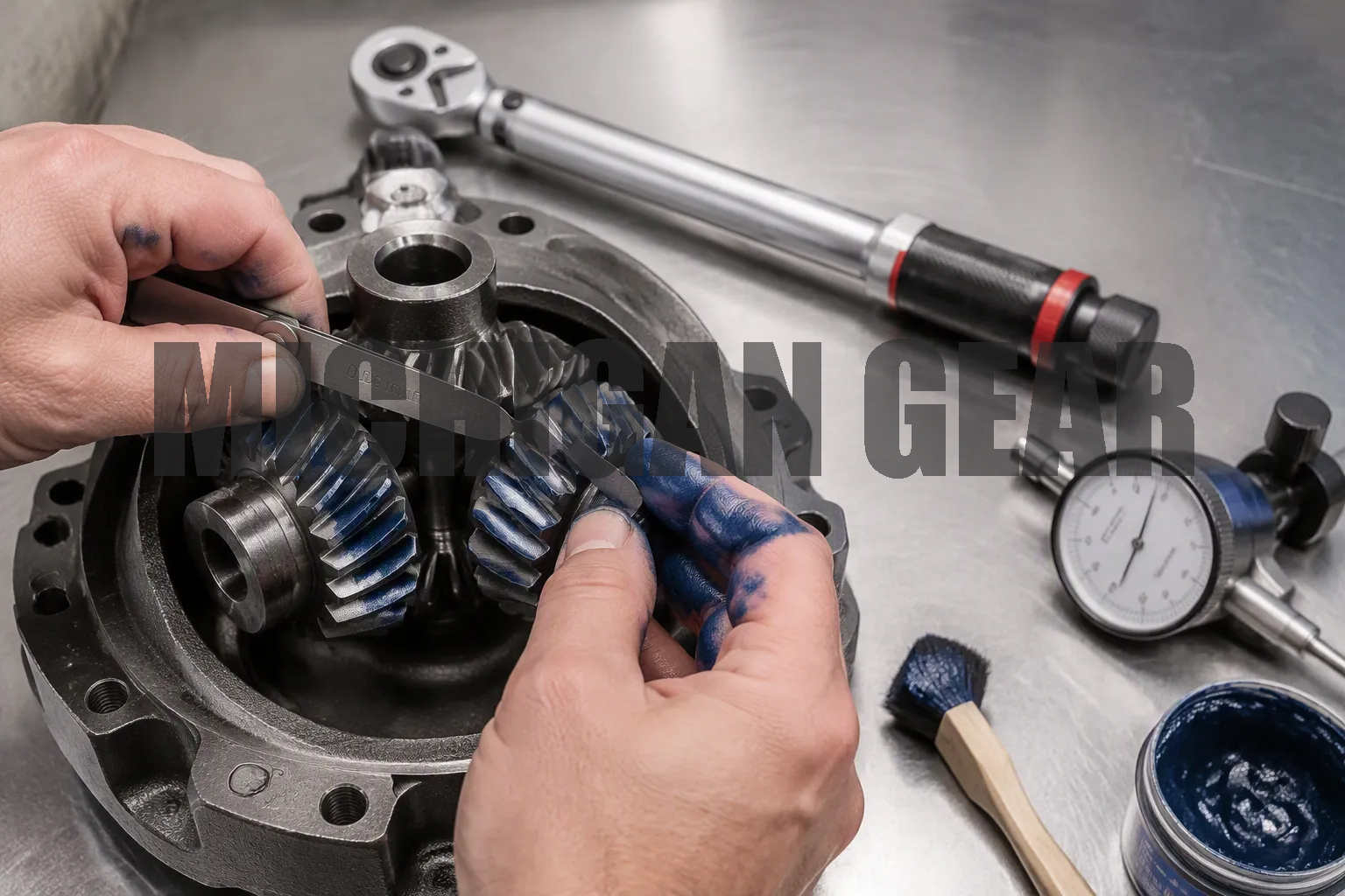
Contact pattern describes the shape and location of tooth contact during operation. I check this by applying marking compound to the teeth and rotating the pair under light load. The resulting mark shows where the teeth actually touch. A good pattern sits centered on the tooth flank and covers a healthy portion of the surface. A pattern shifted toward the heel or toe signals misalignment. A pattern concentrated at the tip or root indicates incorrect mounting distance.
The table below distinguishes these three terms at a glance.
| Term | Definition | Unit of Measure | Primary Effect |
|---|---|---|---|
| Backlash | Clearance between meshing teeth | Linear (mm or inch) | Noise, heat, reversal impact |
| Tolerance | Allowable dimensional variation | Grade or class number | Mesh consistency |
| Contact Pattern | Shape and location of tooth contact | Visual assessment | Load distribution, wear |
Why Miter Gear Performance Depends on These Factors
Effects of Too Little or Too Much Backlash
Backlash that runs too tight creates serious problems. The mesh runs tight, generates heat, and loses its oil film. Metal-to-metal contact follows, and the teeth wear quickly. I have seen gear sets fail in weeks when backlash was set near zero without accounting for thermal growth.
Too much backlash causes the opposite problem. The gear pair feels loose. Every direction reversal produces impact loading. That shock load damages tooth flanks and shortens service life.
The best practice is to limit backlash to the minimum value needed for tolerances, misalignment, and lubrication. This value is not zero. It is the smallest gap that still allows an oil film and absorbs manufacturing variation.
Center distance changes affect both backlash and contact ratio. Decreasing the mounting distance reduces backlash, but it also alters the contact pattern. For small miter gears, achieving near-zero backlash depends on whether the teeth are straight or spiral. Spiral teeth generally allow tighter settings because more teeth share the load at any moment.
How Tolerance and Contact Pattern Affect Mesh Quality
Tolerance determines how precisely gears fit together. Poor tolerance leads to inconsistent mesh from one unit to the next. A tightly controlled gear can still mesh poorly in a flexible or misaligned housing. Housing alignment, center-distance tolerance, bearing clearance, and temperature all interact with gear positioning. Machining errors such as non-coplanar bearing bore axes cause persistent contact issues that require scraping or rework.
Contact pattern reveals mesh quality directly. I check it with marking compound under light load. A heel-weighted pattern on spiral miter gears usually means the pinion sits too far out or the gear too far in. I correct this by moving the pinion in and the gear out, following the tooth ratio so backlash stays within limits. The gear adjustment should approximately follow the ratio of gear teeth to pinion teeth. I check backlash continuously because axial movement changes it.
| Observed static pattern fault | Likely assembly cause | Corrective axial adjustment |
|---|---|---|
| Pattern too close to heel on concave flank | Pinion too far out or gear too far in | Move pinion in / move gear out |
| Pattern too low near root on tooth | Pinion too far in or gear too far out | Move pinion out / move gear in |
Mounting distance is the axial distance from a reference point on the gear to its theoretical cone apex. In an ideal setup, the cone apexes of both pinion and gear coincide. When actual mounting distances deviate, the apexes do not align, and non-conjugate tooth contact results. This misalignment produces contact patterns that are symmetrical on both flanks of the pinion, unlike other errors that cause asymmetric contact.
What Buyers and Engineers Should Specify
Practical Guidance for Choosing a Supplier
I always tell buyers to specify three things before placing an order: backlash range, tolerance class, and acceptable contact pattern. These specifications prevent costly mistakes later.
For general automation and packaging applications, backlash of 0.08–0.15 mm works well. Servo and positioning drives need tighter control at 0.03–0.08 mm with matched pairs. I warn against specifying zero backlash on the gear itself. A split or spring-loaded gear handles that requirement better. If you call out backlash on the pitch circle without defining working depth or center distance, the number means nothing. The shop needs the whole pair geometry.
Tolerance class matters just as much. AGMA 8 covers most general industrial drives. AGMA 10–12 suits servo axes and high-speed spindles. These higher classes usually require grinding after heat treatment. If I add only one tolerance to a gear drawing, I make it radial runout relative to the bore.
Contact pattern acceptance deserves explicit attention. For high-power miter gears, I specify that the pattern should cover at least 70–80% of the active tooth flank under test load. The pattern must sit centered with no extreme biasing toward the toe or heel. Standards like ANSI/AGMA 2009-B01 define the contact zone on drawings with strict requirements for shape, location, size, and boundary conditions.
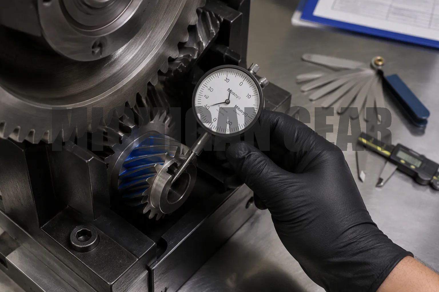
I ask suppliers for test reports before I approve any shipment. Single flank inspection rolls the gear at design center distance with a master gear. Double flank testing measures center distance variation. CMM charts verify profile, helix, and pitch accuracy. Hardness test reports confirm proper heat treatment. A qualified supplier provides these documents without hesitation.
Buyers should also ask specific quality control questions. What is the maximum gear precision you achieve? Which inspection technologies do you use routinely? Do you supply gears as matched pairs? How do you define your measurement protocol? These questions reveal whether a supplier controls backlash through tooth thickness, center distance, or mounting distance adjustment.
Who Needs This Information and What Happens If Parameters Are Wrong
Design engineers, maintenance technicians, procurement specialists, and hobbyists building gear systems all benefit from this knowledge. Each group faces different consequences when parameters go wrong.
Wrong backlash settings cause premature failure. Too little clearance generates heat and destroys the oil film. Too much clearance creates impact loading during direction reversal. Both conditions lead to costly downtime.
Incorrect tolerance classes produce inconsistent mesh from one unit to the next. Excessive noise follows. Heat builds up. Efficiency drops. The entire system underperforms.
Poor contact patterns concentrate stress on a small tooth area between the heel and toe. Wear accelerates. Teeth may crack or break under load.
A qualified supplier can verify your specifications and recommend adjustments. I always encourage buyers to share their application details early. The right supplier will confirm whether your backlash target, tolerance class, and contact pattern requirements match real-world performance needs. Contact a qualified gear supplier today to verify your specifications and ensure optimal performance.
Backlash, tolerance, and contact pattern work together. They decide noise, wear, heat, and efficiency in every miter gear set. Wrong settings cause premature failure, costly downtime, and poor performance. Use the guidance above when you specify or purchase gears. Contact a qualified gear supplier today to verify your specifications and ensure optimal performance.
FAQ
How do I measure backlash on my miter gear set?
I clamp one gear stationary. I place a dial indicator against the other. I rock it and read the movement.
Can I adjust backlash after installation?
Yes. I move one gear axially to change the mounting distance. I check the contact pattern after each adjustment to preserve mesh quality.
What is the most common contact pattern mistake during assembly?
I see operators skip the check. A poor pattern concentrates stress on a small area. Wear accelerates fast. Gears fail early.
Post time: Sep-14-2026