


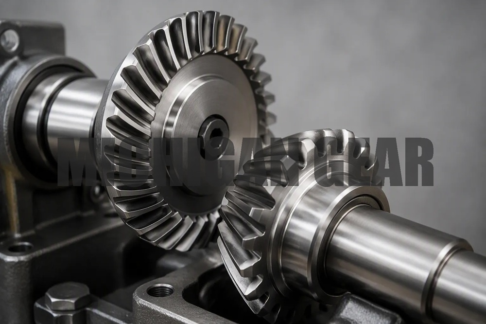
Need to rotate a shaft 90 degrees without changing speed? I have the solution: a miter gear. This specialized gear delivers a fixed 1:1 ratio for a right-angle drive. In this guide, I explain how this miter gear works, its applications, and how to select one for your drive. It simplifies your design and ensures efficient power transfer.
Key Takeaways
●Miter gears change direction by 90 degrees without changing speed or torque.
●Choose miter gears for compact, efficient right-angle drives with a 1:1 ratio.
●Select miter gears over hypoid gears for higher efficiency and simpler lubrication.
What Is a Miter Gear?
The Miter Gear Definition and 1:1 Ratio
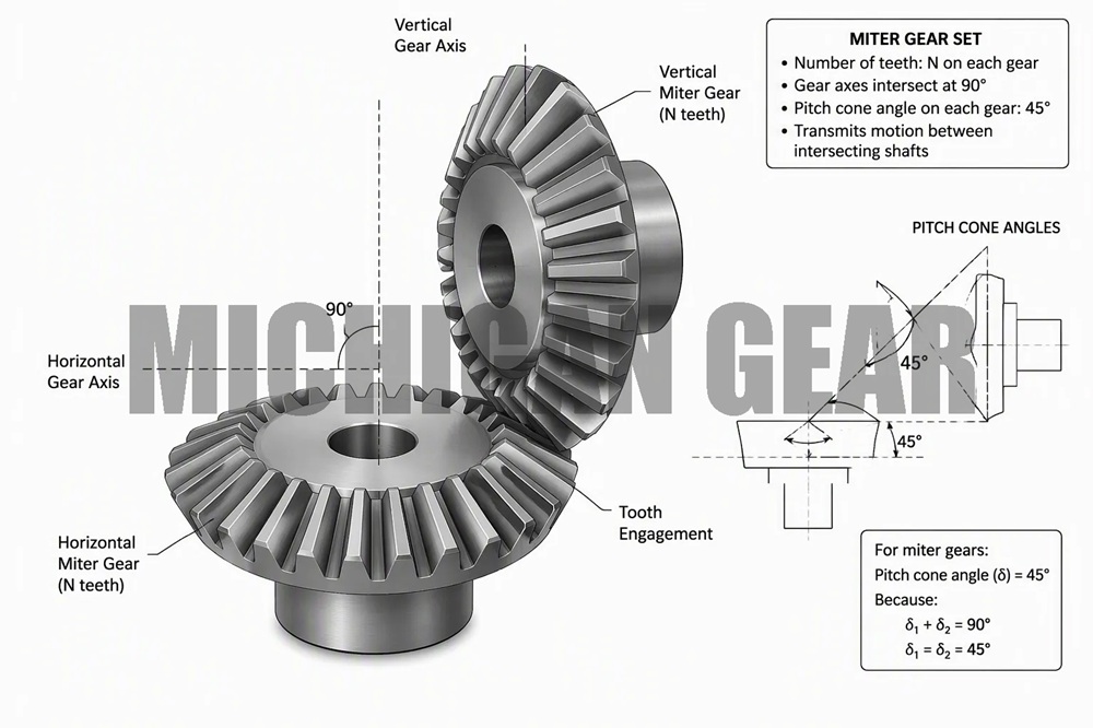
A miter gear is a specialized type of bevel gear. I want you to understand this key point: a miter gear operates at a fixed 90-degree shaft angle with a constant 1:1 ratio. This means both components in the pair have the same number of teeth. The pitch cone angle for each component measures exactly 45 degrees. This specific angle ensures the two conical pitch surfaces meet at the intersection point of the perpendicular shafts. The result is a smooth power transfer that changes direction by 90 degrees without altering speed or torque. The anatomy of a miter bevel gear set includes equal tooth counts on both components, equal pitch cone angles of 45 degrees each, and a fixed shaft angle of 90 degrees. This configuration delivers pure direction change with no speed or torque modification. The teeth can be straight or spiral, but the core geometry remains the same. A miter gear is the simplest right-angle gear solution for a 1:1 drive because it requires no complex calculations for ratio selection.
How a Miter Bevel Gear Set Works
A miter bevel gear set transmits torque through a specific mechanical action. Both components have identical tooth counts. I mount them in the same plane with intersecting axes. This arrangement redirects the rotational motion by 90 degrees. The speed and torque values stay the same on both shafts. For straight-tooth variants, the loading remains purely radial. This allows me to use standard radial bearings in the assembly. The tooth contact pattern differs between straight and spiral miter bevel gear set designs. Let me explain the key differences in a table.
| Criterion | Straight Type | Spiral Type |
|---|---|---|
| Tooth Contact | Abrupt line contact, single point engagement | Gradual point-to-line contact, smooth engagement |
| Noise & Vibration | High noise and vibration, especially at higher speeds | Low noise and vibration, quiet operation |
| Load Capacity | Moderate, suitable for low to moderate speeds and torque | Higher load capacity, better distribution at high speeds |
| Manufacturing Complexity | Simple design, easier to machine, lower cost | Complex curved geometry, requires high precision, higher cost |
| Wear & Lubrication | Higher wear due to direct impact; proper lubrication critical | Lower wear, longer service life with proper lubrication |
Straight and zerol types allow me to mate the same two components together without issue. Spiral types require pairing a left-handed component with a right-handed component. Both configurations maintain the 1:1 ratio and 90-degree shaft angle. The choice depends on my application speed requirements. I select straight for low to moderate speeds. I choose spiral for high-speed applications where quiet operation matters. Each miter gear configuration offers different advantages based on the operating conditions. When I select a miter bevel gear set, I consider the speed requirements first.
Selecting the Right Miter Gear
Miter Gears vs. Other Bevel Gears
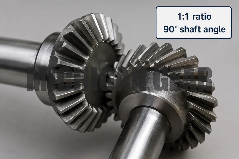
I often see engineers confuse miter gears with other bevel gear types. The distinction matters for your application. A miter bevel gear set always delivers a 1:1 ratio with a 90-degree shaft angle. Other bevel gears offer different ratios and shaft angles. Straight bevel gears can provide various ratios, but they lack the fixed 1:1 configuration. Spiral bevel gears share the same geometry but allow ratio variations beyond 1:1.
The real comparison comes when you consider hypoid gears. Hypoid gears operate with offset shafts, not intersecting ones. This offset creates sliding action between teeth. That sliding reduces efficiency and increases heat. A miter bevel gear set operates on the same plane with intersecting shafts. This design eliminates the offset entirely. The result is higher torque and speed capacity. Spiral miter gears achieve efficiency ratings up to 99%. Hypoid gears only reach 90-95%. Hypoid gears also require special extreme-pressure lubricants. Miter gears work with standard gear grease or oil. This difference simplifies maintenance and cuts operational costs.
Hypoid gears do not offer 1:1 or 2:1 ratios. Miter gears provide both options. For a true 1:1 right-angle gear drive, miter gears remain the only viable choice. They also transfer power left, right, or bidirectionally. They support counter-rotational operation. This flexibility makes them ideal for space-constrained applications.
Key Factors for Sourcing a Miter Gear
When I source a miter gear, I evaluate several critical factors. These criteria determine whether the gear performs reliably in your specific application.
●Shaft orientation: Confirm your shafts intersect at 90 degrees. A direction change must be required.
●Reduction range: Verify you need a 1:1 ratio. Moderate reduction needs point to other gear types.
●Space constraints: Check axial length limits. Right-angle packaging often favors miter gears.
●Efficiency and thermal sensitivity: Assess heat management needs. Miter gears run cooler than hypoid alternatives.
●Load direction and duty cycle: Consider continuous duty, shock loading, or reversing motion.
●Operating environment: Evaluate temperature, lubrication, and contamination exposure.
Beyond these application factors, I provide detailed gear data to suppliers. This information prevents costly mistakes during quotation.
●Ratio: Confirm 1:1 or another required ratio. This determines whether miter gears fit your needs.
●Shaft angle: Specify 90 degrees or a custom angle. This affects tooth geometry and mounting.
●Gear data: Include tooth count, module or diametral pitch, pressure angle, face width, bore, keyway, or spline.
●Material and heat treatment: State steel grade, hardness, case depth, or approved alternatives.
●Backlash requirement: Provide the drawing value or acceptable range. This controls assembly feel and meshing.
●Application details: Share load, speed, lubrication, machine type, and failure symptoms.
●Inspection needs: Define dimensional reports, hardness checks, contact verification, or tooth geometry reports.
Each factor plays a role in the final selection. I always match the gear material to the operating environment. I verify the bore size matches my shaft diameter. I confirm the mounting arrangement suits my housing. These steps ensure the miter bevel gear set performs as expected. The right choice delivers years of reliable service.
A miter gear offers the simplest path for a 1:1 right-angle drive. This right-angle gear delivers high efficiency in a compact package. Remember, it requires precise alignment and a fixed ratio. Assess your shaft size, load, and speed needs. Then consult a gear supplier’s catalog or an engineer for final selection.
FAQ
Can I use a miter gear for speed reduction?
No. A miter gear always delivers a 1:1 ratio. It changes direction only, never speed or torque. For reduction, you need a different bevel gear type.
How do I align a miter bevel gear set properly?
I align both shafts at exactly 90 degrees. I check the tooth contact pattern. I adjust the mounting distance until teeth mesh smoothly across the full face width.
What lubrication does a miter bevel gear set require?
I use standard gear oil or grease. Unlike hypoid gears, this gear does not need special extreme-pressure lubricants. Regular maintenance keeps the gear running quietly and efficiently.
Post time: Aug-28-2026