


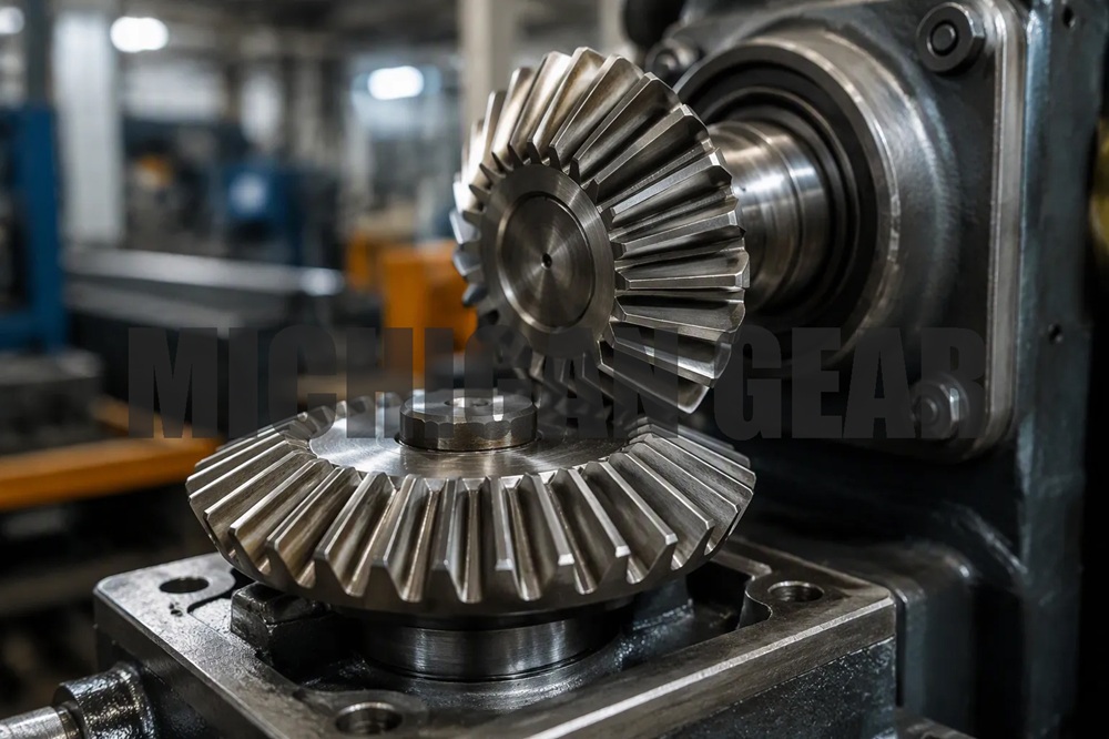
I notice miter gears all around me once I pay attention. These are special bevel gears with a 1:1 ratio, moving power between shafts at a perfect 90-degree angle. They shift direction but keep speed and torque the same. I spot them in hand drills and angle grinders, as well as big equipment. They provide 92–98% efficiency, outperforming flexible cables. Let me look at seven industrial uses where this special mix makes the Miter Gear the best pick, then cover benefits and how to choose one.
Key Takeaways
- Miter gears turn power at a 90-degree angle without altering speed. They suit cramped areas and perform effectively in various machines.
- Setting up miter gears correctly and keeping them lubricated helps them run smoothly. Check that they line up right and look at how they touch to prevent failures.
- Pick miter gears when speed stays the same. Use standard bevel gears if you need to change speed up or down.
Miter Gear Applications in Industrial Machinery
Packaging, Material Handling, and Conveyor Systems
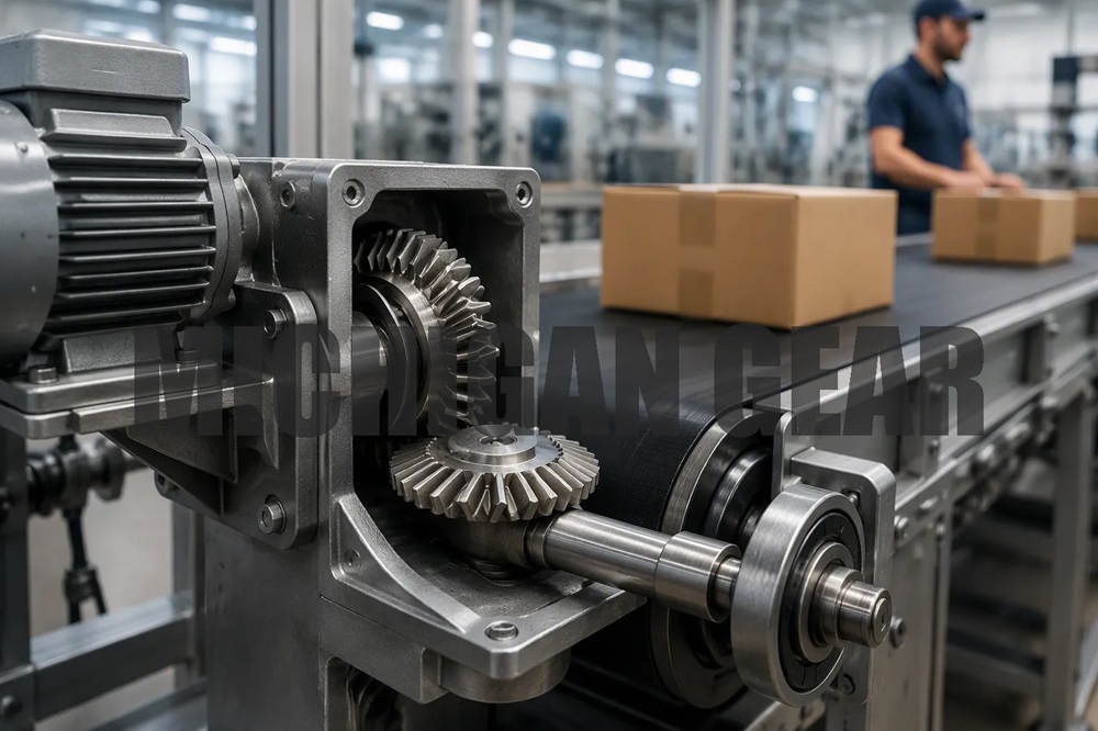
I see miter gears working all the time inside packaging lines and sortation conveyors. These systems need compact right-angle drives that keep a steady speed. A Miter Gear works great when space is tight and operators need a reliable 90-degree turn without changing speed. I find them in auxiliary drives that send power from a main motor to side rollers or transfer parts. They keep the line moving smoothly without adding heavy gearboxes.
The torque needs change a lot across these uses. I can pick a small unit for light package handling or a huge setup for heavy pallet loads. The range goes from 0.1 Nm to 50,000 Nm, which covers almost every conveyor situation I run into. Speed matters too. Straight-cut bevel gears handle jobs below 1,000 RPM, while spiral bevel versions run above 1,500 RPM. A common rating I see often is 220 Nm at 1,500 RPM input, which fits many mid-sized conveyor drives.
Maintenance keeps these systems working. I learned that most gear failures come from lubrication issues. Not enough oil, wrong oil type, dirt, or foaming all cause breakdowns. When the oil film fails, scoring and galling happen, and metal rubbing on metal creates high heat. I use a simple checklist for setup. First, I check shaft alignment carefully before final assembly. Then I check the contact pattern across the gear teeth. After startup, I watch for small vibrations, odd noises, or slower performance over time. I look for minor surface pitting during regular maintenance. For lubricant choice, I pick oils or greases made for specific temperatures, loads, and speeds. I follow manufacturer instructions closely. High-speed systems need more frequent checks, so I use condition-based maintenance plans. Regular inspections catch problems before big failures, making gears last longer and cutting downtime.
Machine Tools, Robotics, and Automotive Systems
Machine tool indexing needs very precise miter gears. I see parts reaching DIN 4 grade pitch accuracy, which is very good quality for small-module gears. The single pitch error stays below the DIN 4 limit for both gear and pinion. Tooth flank shape errors measure 5.4 μm for the gear and 7.4 μm for the pinion, both well under the 7.5 μm limit. These precision levels meet the needs for noise, vibration, and torque in indexing jobs.
Robotic joint movement brings special design challenges. I mount motors at right angles to joint axes, and a Miter Gear pair turns power at 90 degrees. This setup shortens the drive assembly length, allowing slim housings and cleaner cable paths. In robot wrists, coaxial shafts drive a series of miter gears for yaw joints. Secondary stages handle speed reduction. Robotic grippers benefit too. I place motors parallel to the palm, and right-angle bevel pairs drive lead screws or rack-and-pinion rails. This stops motor body sticking out and allows synchronized two-finger motion with direct force feedback. Mobile robots use vertical motor mounting inside wheel pods. The miter gear pair turns rotation to horizontal wheel axles, reducing horizontal space. Humanoids and exoskeletons mount motors vertically inside leg frame channels. The gear setup turns rotation into hip, ankle, or knee pivot shafts, keeping limb width small.
Automotive steering systems also depend on these gears. Vertical pump drives and feed systems keep strict 1:1 ratios that are vital for proper operation. I trust miter gears in these uses because they give predictable, repeatable performance.
Why Choose a Miter Gear for 90-Degree Transmission?
Key Benefits and Inherent Limitations
Miter gears have several clear benefits for right-angle power transfer. Their identical pitch cone angles make processing simpler, which lowers manufacturing costs compared to standard bevel gears. Installation is also easier because miter gears are interchangeable and allow flexible assembly. There is no need to fine-tune meshing positions like with other gear types. The compact structure fits tight spaces in tools such as hand drills and angle grinders. Constant speed transmission means reliable 90-degree direction changes without unexpected speed drops.
| Advantage | Supporting Detail |
|---|---|
| Easier processing | Identical pitch cone angles allow same processing settings |
| Easier installation | Flexible assembly and interchangeability |
| Compact structure | Only changes direction, enabling small designs |
| Constant speed | Maintains rotational speed during power transmission |
However, limitations exist. The fixed 1:1 ratio means speed cannot be changed at all. Both gears have equal tooth counts, so high-speed applications get no speed variation. Axial thrust also appears during operation. This force pushes gears apart and requires ball or sleeve bearings to absorb it. At higher speeds, thrust increases and adds stress on bearing systems, possibly limiting maximum operating speeds.
Miter Gear vs. Standard Bevel Gear: A Critical Distinction
The key difference comes down to ratio flexibility. A Miter Gear always delivers a 1:1 transmission ratio with equal tooth counts on both gears. Standard bevel gears accept various ratios, typically from 2:1 up to 6:1 for straight tooth designs. This distinction matters when selecting components for specific jobs.
| Feature | Miter Gear | Standard Bevel Gear |
|---|---|---|
| Shaft angle | Fixed at 90° | Typically 90°, but variable |
| Transmission ratio | Always 1:1 | Can be any ratio |
| Tooth count | Equal on both gears | Usually different |
| Pitch cone angles | Equal, often 45° each | Typically unequal |
| Main function | Direction change only | Direction change plus speed change |
When pure direction change is needed without altering speed, a Miter Gear is the choice. When an application requires speed reduction or increase alongside the 90-degree turn, a standard bevel gear is better. Applications needing ratios between 3:1 and 6:1 work better with bevel gears due to space constraints. This clear separation guides component selection every time.
These seven applications share one common thread. Each needs reliable, efficient, and compact 1:1 right-angle power transmission. I value miter gears for their simplicity and predictable performance. They deliver dependable direction changes without complex speed adjustments. When I need a 90-degree turn with strict 1:1 ratio, this gear offers the most straightforward and economical solution available.
FAQ
How do I know if a Miter Gear fits my application?
Check your speed requirements first. If you need a strict 1:1 ratio with a 90-degree turn, this gear works perfectly. If you need speed changes, choose a standard bevel gear instead.
What maintenance keeps miter gears running smoothly?
I check shaft alignment before assembly and verify the contact pattern across gear teeth. Regular lubrication checks prevent most failures. I watch for vibrations, odd noises, or performance drops during operation.
Can I use miter gears at high speeds?
Straight-cut miter gears handle speeds below 1,000 RPM. Spiral bevel versions run above 1,500 RPM. I match the gear type to your operating speed range for reliable performance.
Post time: Sep-08-2026